


Regency
®
L234 Direct Vent Gas Insert
12
INSTALLATION
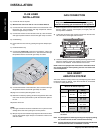
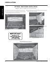
GAS INSERT
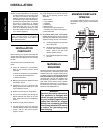
AERATION SYSTEM
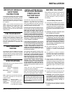
The burner aeration is factory set but may need adjusting due to either
the local gas supply or altitude. Open the air shutter for a blue fl ame
or close for a more yellow fl ame.
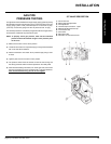
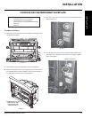
GAS CONNECTION
GAS CONNECTION WARNING:
Only persons licensed to work with gas piping may
make the necessary gas connections to this appliance.
1) When the appliance is to be installed into either an existing masonry
chimney system or factory built fi replace, thoroughly clean the
chimney before installation.
2) A 3/8" NPT gas supply pipe must be brought near the inlet hole.
The valve inlet is on the right side of the unit.
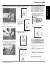
3) Locate the center point where the vent will pass through the chimney
above the appliance. Move the appliance into the exact location
where it is to be installed. Ensure that the Insert is level.
NOTE: This unit is equipped with a heat sensor thermodisc which
will prevent the blower from operating until the unit reaches the
correct temperature.
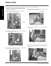
5) Install fl ashing.
6) Insert both liners into chimney, passing through the damper open-
ing.
7) Install termination cap.
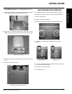
8) Connect the marked end of the liner to the exhaust collar of the
vent connector plate marked with an "E", seal connection with high
temperature silicone. Secure with gear clamp or screws.
NOTE:
1) Final gas connection should be made after unit is in place to avoid
damage to the liner when pushing the unit into position.
2) Mill-pac may be used instead of high tempture silicone and screws
may be used instead of gear clamps at connections of liner to inlet
and vent collars.
9) Connect the 2nd liner to the intake collar, seal connection with high
temperature silicone. Secure with gear clamp or screws.
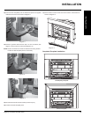
10) Align vent connector plate with guides on unit.
11) Slide unit into masonry opening, while ensuring that the slots at the
rear of the connector plate mates up with the hold down plate on
the unit.
12) Secure with screw.
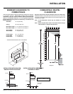
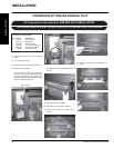
FLUE LINER
INSTALLATION
1) Cut the fl ex liner as required.
2) Mark the end of one liner with an "E" to indicate Exhaust.
3) Connect the other end of the above liner to the exhaust side of the
termination cap, seal connection with high temperature silicone.
Secure with gear clamp or screws.
4) Connect the 2nd liner to the inlet side of the cap, seal connection
with high temperature silicone. Secure with gear clamp or screws.
INSTALLATION
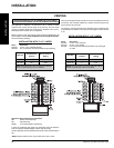
Minimum Air Shutter Openings
Vent Run
Burner Aeration
Setting
3" x 3"
8' to 20'
NG: 3/16"
LP: 3/16"
20' to 35'
NG: 3/16"
LP: 3/16"
3" x 2"
8' to 20'
NG: 3/16"
LP: 3/16"
20' to 35'
NG: 1/8"
LP: 1/8"
CAUTION: Carbon will be produced if the air shutter is closed
too much.
Note: Any damage due to carboning resulting from improperly setting
the aeration controls is NOT covered under warranty.
Note: Aeration Adjustment should only be performed by an authorized
FPI Installer at the time of installation or service.