


Regency
®
L234 Direct Vent Gas Insert
28
INSTALLATION
INSTALLATION
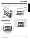
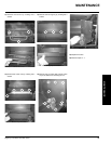
Use of FPI Remote Control Kit #910-399 or
#910-368 is approved for this unit. Use of other
systems may void your warranty.
The remote control kit comes with a hand held
transmitter, a receiver and a wall mounting
plate.
OPTIONAL REMOTE
CONTROL
OPTIONAL WALL
THERMOSTAT
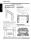
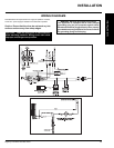
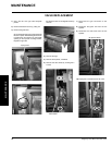
A wall thermostat may be installed if desired,
follow the wiring diagram below. Note: the wires
are connected to the "TH" on the gas valve. Use
the table below to determine the maximum wire
length. FPI offers an optional programmable
thermostat but any 250-750 millivolt rated non-
anticipator type thermostat that is CSA, ULC
or UL approved may be used.
It is recommended that the thermostat be
installed on an interior wall.
CAUTION
Do not connect the millivolt
wall thermostat wires
to the 120V wires.
14 GA.
16 GA.
18 GA.
20 GA.
22 GA.
50 Ft.
32 Ft.
20 Ft.
12 Ft.
9 Ft.
Recommended Maximum Lead Length
(Two-Wire) When Using Wall
Thermostat (CP-2 System)
Wire Size Max. Length
Thermostat Wire Table
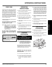
FINAL CHECK
Before leaving this unit with the customer, the
installer must ensure that the appliance is fi ring
correctly. This includes:
1) Clocking the appliance to ensure the
correct fi ring rate (rate noted on label) at
15 minutes.
2) If required, adjusting the primary air to ensure
that the fl ame does not carbon. First allow
the unit to burn for 15 min. to stabilize.
3) Check for proper draft.
CAUTION
Any alteration to the product that
causes sooting or carboning that
results in damage to the exterior
facia is not the responsibility of
the manufacturer.
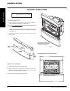
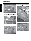
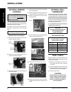
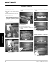
1) Remove the control switch from the remote
receiver by gently pulling out.
Control
Switch
2) Remove the spring loaded battery pack by
pushing in and then pulling out.
Remote
Receiver
3) Remove the receiver from the bracket and
discard the bracket.
Battery
Pack
Bracket
Receiver
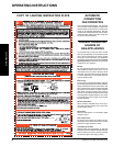
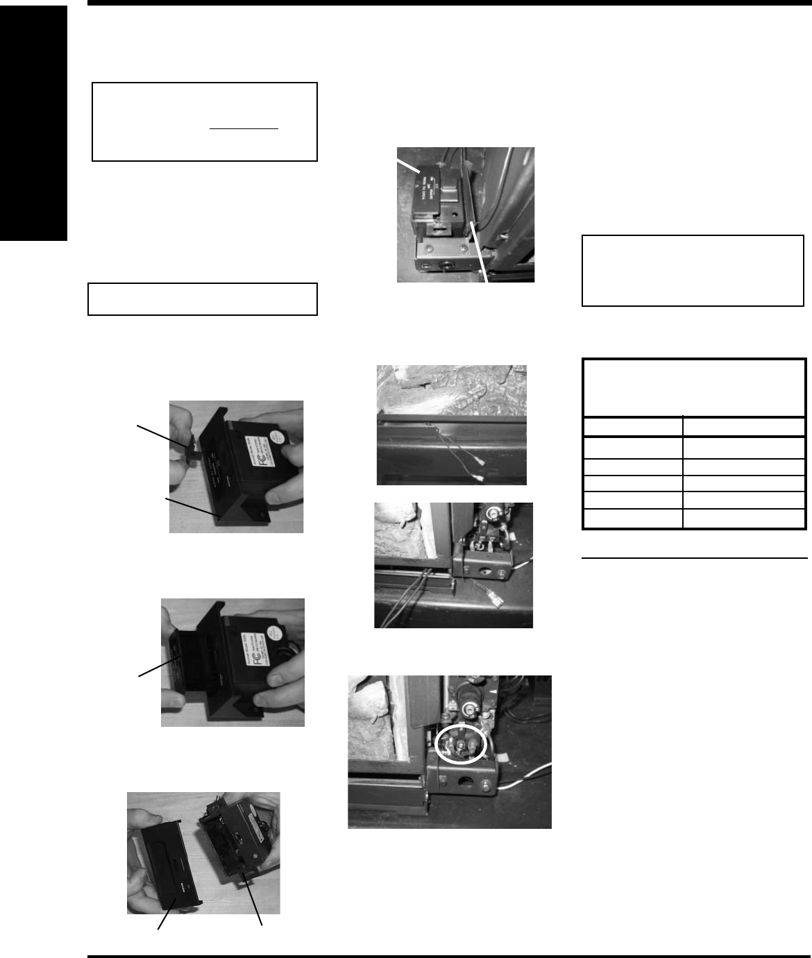
Remote Receiver Installation
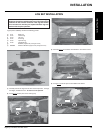
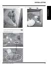
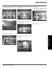
6) Secure the receiver to the velcro on the
recevier bracket.
7) Run the receiver wires under the base of the
fi rebox to the left side of the unit.
Receiver Bracket
Receiver
8) Connect the reciever wires to the valve.
4) Re-install the control switch and the battery
pack (with batteries).
5) Remove the peel off from the velcro on the
receiver bracket on the left side of the unit.
9) Secure the loose wires under the fi rebox
in the wire clips located on the base of the
fi rebox.
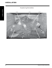
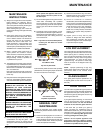
IMPORTANT
Due to the extreme heat this gas insert
emits, brick panels are required to be
installed in the unit when using either
remote control option.
Refer to Remote Control manual for complete
user setup and operation instructions.