


UltraGlow
®
G36D Zero Clearance Direct Vent Gas Fireplace
21
INSTALLATION
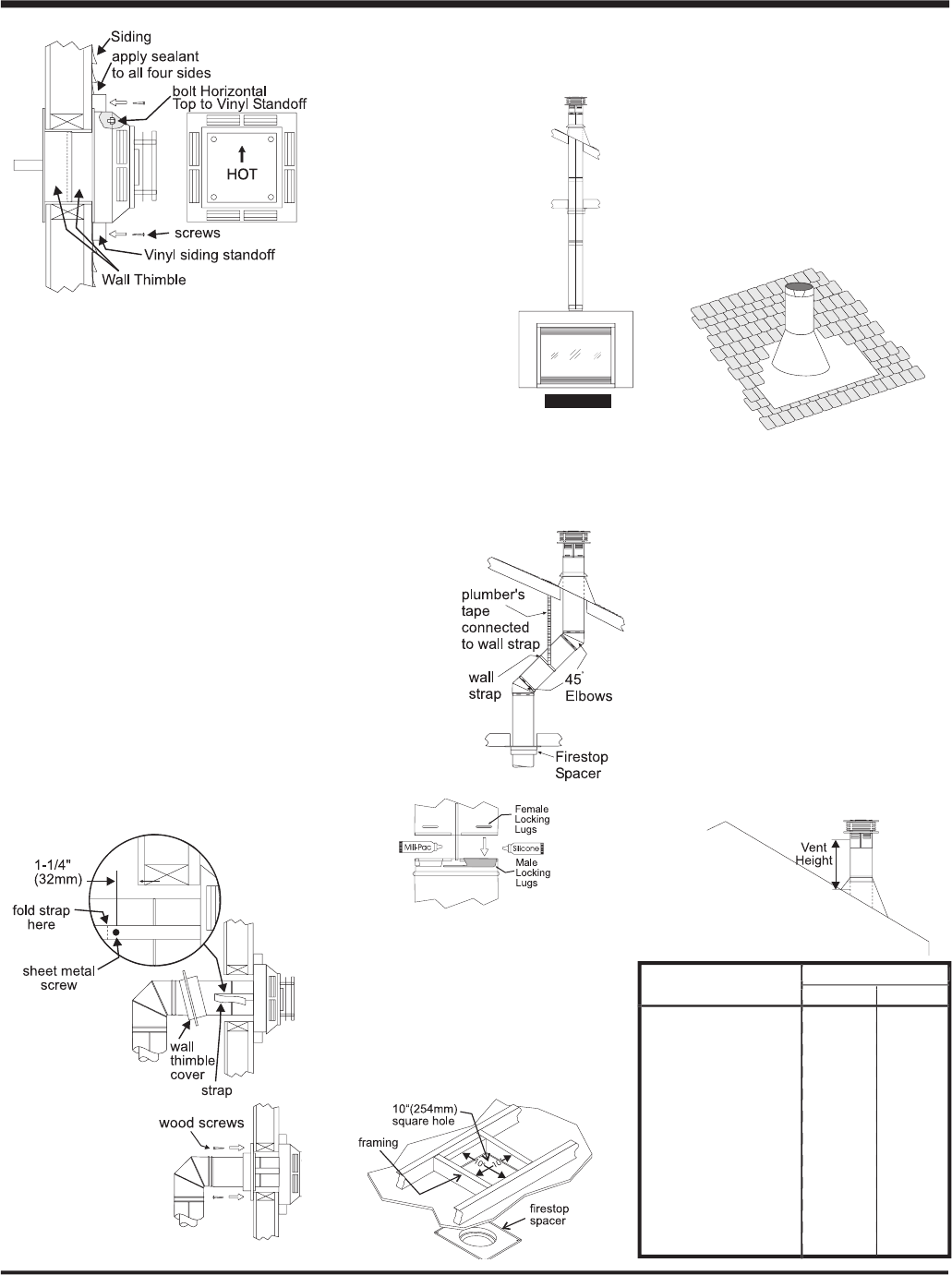
Diagram 3
Diagram 5
Diagram 1
Diagram 2
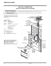
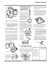
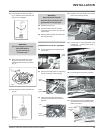
Note: Apply sealant "Mill-Pac" to inner pipe
and high temperature silicone seal-
ant to outer pipe on every twist-lock
joint.
Diagram 5
Diagram 6
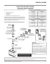
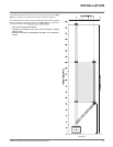
UNIT INSTALLATION
WITH VERTICAL
TERMINATION
1)
Maintain the 1-1/2" clearances
(air spaces) to combustibles
when passing through ceilings,
walls, roofs, enclosures,
attic rafter, or other nearby
combustible surfaces. Do not
pack air spaces with insulation.
Check the "Venting" section for
the maximum vertical rise of
the venting system and
the maximum horizontal
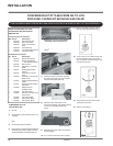
Diagram 7
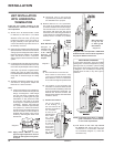
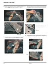
The four wood screws provided should
be replaced with appropriate fasteners for
stucco, brick, concrete, or other types of
sidings.
Note: If installing termination on a siding
covered wall, a vinyl siding standoff
or furring strips must be used to
ensure that the termination is not
recessed into the siding.
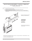
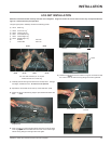
7)
Before connecting the horizontal run of vent
pipe to the vent termination, slide the Wall
Thimble (Part # 942) over the vent pipe.
8)
Slide the appliance and vent assembly
towards the wall carefully inserting the
vent pipe into the vent cap assembly. It is
important that the vent pipe extends into
the vent cap suffi cient distance so as to
result in a minimum pipe overlap of 1-1/4
inches. Secure the connection between the
vent pipe and the vent cap by attaching the
two sheet metal strips extending from the
vent cap assembly into the outer wall of the
vent pipe. Use the two sheet metal screws
provided to connect the strips to the pipe
section. See Diagram 6.
9)
Install wall thimble in
the center of the 10"
square and attach
with wood screws
(Diagram 7).
offset limitations.
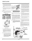
2)
Set the gas appliance in its
desired location. Drop a
plumb bob down from the
ceiling to the position of
the appliance fl ue exit, and mark the location
where the vent will penetrate the ceiling. Drill
a small hole at his point. Next, drop a plumb
bob from the roof to the hole previously drilled
in the ceiling, and mark the spot where the
vent will penetrate the roof.
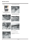
Determine if
ceiling joists,
ceiling joists,
roof rafters or
other framing
will obstruct
the venting
system. You
may wish to
relocate the
a p p l i a n c e
or to offset,
as shown in
Diagram 2 to
avoid cutting
load bearing
members.
3)
A Firestop spacer must be installed in the
fl oor or ceiling of every level. To install the
Firestop spacer in a fl at ceiling or wall, cut a
10 inch square hole. Frame the hole as shown
in Diagram 3 and install the fi restop.
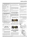
4)
Assemble the desired lengths of pipe and
elbows. Ensure that all pipes and elbow
connections are in the fully twist-locked
position and sealed.
5)
Cut a hole in the roof centered on the small
drilled hole placed in the roof in Step 2. The
hole should be of suffi cient size to meet
the minimum requirements for clearance
to combustibles of 1-1/2". Slip the fl ashing
under the shingles (shingles should overlap
half the fl ashing) as per Diagram 4.
Diagram 4: The upper half of the fl ashing is
installed under the roofi ng material and not
nailed down until the chimney is installed. This
allows for small adjustments.
6)
Continue to assemble pipe lengths.
Note: If an offset is necessary in the attic
to avoid obstructions, it is important
to support the vent pipe every 3 feet,
to avoid excessive stress on the
elbows, and possible separation.
Wall straps are available for this
purpose (Diagram 2).
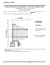
Galvanized pipe is desirable above the
roofl ine due to its higher corrosion resistance.
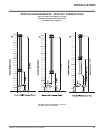
Continue to add pipe sections through the
fl ashing until the height of the vent cap meets
the minimum height requirements specifi ed
in Diagram 5 or local codes. Note that for
Roof Pitch Minimum Vent Height
Roof Pitch Minimum Vent Height
Roof Pitch Minimum Vent Height
Roof Pitch Minimum Vent Height
Feet Meters
Feet Meters
Feet Meters
Feet Meters
fl at to 7/12 2 0.61
fl at to 7/12 2 0.61
fl at to 7/12 2 0.61
fl at to 7/12 2 0.61
over 7/12 to 8/12 2 0.61
over 7/12 to 8/12 2 0.61
over 7/12 to 8/12 2 0.61
over 7/12 to 8/12 2 0.61
over 8/12 to 9/12 2 0.61
over 8/12 to 9/12 2 0.61
over 8/12 to 9/12 2 0.61
over 8/12 to 9/12 2 0.61
over 9/12 to 10/12 2.5 0.76
over 9/12 to 10/12 2.5 0.76
over 9/12 to 10/12 2.5 0.76
over 9/12 to 10/12 2.5 0.76
over 10/12 to 11/12 3.25 0.99
over 10/12 to 11/12 3.25 0.99
over 10/12 to 11/12 3.25 0.99
over 10/12 to 11/12 3.25 0.99
over 11/12 to 12/12 4 1.22
over 11/12 to 12/12 4 1.22
over 11/12 to 12/12 4 1.22
over 11/12 to 12/12 4 1.22
over 12/12 to 14/12 5 1.52
over 12/12 to 14/12 5 1.52
over 12/12 to 14/12 5 1.52
over 12/12 to 14/12 5 1.52
over 14/12 to 16/12 6 1.83
over 14/12 to 16/12 6 1.83
over 14/12 to 16/12 6 1.83
over 14/12 to 16/12 6 1.83
over 16/12 to 18/12 7 2.13
over 16/12 to 18/12 7 2.13
over 16/12 to 18/12 7 2.13
over 16/12 to 18/12 7 2.13
over 18/12 to 20/12 7.5 2.29
over 18/12 to 20/12 7.5 2.29
over 18/12 to 20/12 7.5 2.29
over 18/12 to 20/12 7.5 2.29
over 20/12 to 21/12 8 2.44
over 20/12 to 21/12 8 2.44
over 20/12 to 21/12 8 2.44
over 20/12 to 21/12 8 2.44