March 4, 2002 Page 20 30211C
DV400S DIRECT VENT ROOM HEATER
R
HIGH ALTITUDE INSTALLATION
For U.S. installation, units are tested and approved for elevations
from 0-2000 feet.
When installing this unit at an elevation above 2000 feet, it may
be necessary to decrease the input rating by changing the existing
Burner Orifice to a smaller size. Input should be reduced 4 percent
for each 1000 feet above sea level. Check with the local gas utility
for proper Orifice size identification. This unit is shipped with a
.106 in./2.67 mm Main Burner Orifice size for Natural Gas and a
.063 in./1.60 mm orifice size on Propane Gas versions.
For Canadian installation, units are certified for elevations from
0-4500 feet. When installing this unit at an elevation between
0-4500 feet in Canada, the input rating does not need to be
reduced.
When installing this unit at an elevation above 4500 feet in
Canada, check with local authorities.
Consult your local gas company for assistance in determining the
proper Orifice for your location or refer to ANSI Z223.1-latest edi-
tion, Appendix F.
NOTE: This Heater DOES NOT require a 110VAC sup-
ply for operation.
NOTE: This Heater must be electrically wired and
grounded in accordance with Local Codes or, in the
absence of Local Codes, with the National Electric
Code ANSI/NFPA 70-latest edition, or the Canadian
Electrical Code, CSA C22.1.
NOTE: This appliance and its individual Shut - Off
Valve must be disconnected from the Gas Supply
Piping System during any Pressure testing of that
System at Test Pressures in excess of 1/2 psi (3.5kPa).
The appliance must be isolated from the Gas Supply
Piping System by closing its individual Manual Shut
- Off Valve during any Pressure testing of the Gas
Supply Piping System at test levels equal or less than
1/2 psi (3.5 kPa).
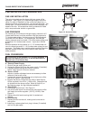
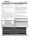
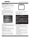
E. Valve - Adjustable Regulator.
1. Gain access to the Valve Regulator Head by lifting up on
the Valve Cover and removing the Tabs from the Slots on the
Back Shield.
2. Follow Steps 1 - 3 in the Instructions included with the
Regulator. Save the Label included in the Kit for later attachment
to the unit.
3. Replace the Valve Cover after the Valve has been checked
for leaks.
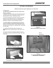
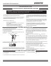
F. Leak Check.
1. Turn on the Gas Supply to the unit to check for gas leaks
with soap and water.
2. Turn the Gas Control Knob to the “Pilot” position.
Push the Knob in all the way and hold. At the same time, push in
the Red Ignitor button repeatedly until the Pilot lights. Never hold
the Gas Control Knob for more than [10] seconds if the Pilot does
not light. Once the Pilot lights, continue to hold the Control Knob
in for 15 seconds. Release the Gas Control Knob and it will pop
back out. Test for leaks at the Pilot Assembly using a soap and
water solution or a a Gas Sniffer. Turn the Gas Control Knob to
the “ON” position and turn the Switch On. Check for leaks around
the Valve and the Burner Orifice.
3. Plug in blower (if installed).
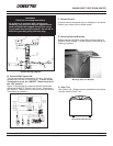
WARNING!
THE INSTALLATION OF THIS
CONVERSION KIT MUST
ONLY BE UNDERTAKEN BY
A QUALIFIED AND CERTIFIED
GAS APPLIANCE INSTALLER.
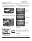
WARNING !
This conversion kit shall be installed by a qualied service agency in accordance
with the manufacturer’s instructions and all applicable codes and requirements of the
authority having jurisdiction. If the information in these instructions is not followed
exactly, a re, explosion or production of carbon monoxide may result causing property
damage, personal injury or loss of life. The qualied service agency is responsible
for the proper installatin of this kit. The installation is not proper and complete until
the operation of the converted appliance is checked as specied in the manufacturer’s
instructions supplied with the kit.


