


R
R
R
September 21, 2006
7014-082B
Page 11
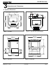
CB 1200 Pellet Stove
Improper installation, adjustment, alteration, service or
maintenance can cause injury or property damage. Refer
to the owner’s information manual provided with this appli-
ance. For assistance or additional information consult a
qualied installer, service agency or your dealer.
WARNING
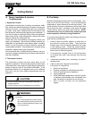
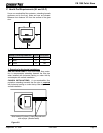
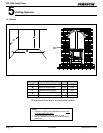
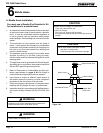
3 in. or 4 in. (76mm or 102mm) Diameter Pipe
Equivalent Pipe
Length In Feet
ALTITUDE IN THOUSANDS OF FEET
0
20
30
1 2 3 4 5 6 7 8 9 10
4 in. (102mm) Diameter Pipe Only
10
The chart will help you in determining proper
venting size according to the equivalent feet of
pipe calculated above and the altitude above sea
level of this installation. See Figure 11.2.
Locate the calculated equivalent feet of pipe on
the vertical left side of the chart. Move to the
right horizontally on the chart until you reach
your altitude above sea level.
If you fall below the diagonal line, or 4 inch (76
to 102mm) pipe may be used. If it is anywhere
above the diagonal line, a 4 inch (102mm) diam-
eter pipe is required.
The chart reveals that a 90° elbow is 5 times as
restrictive to the ow of exhaust gases under
positive pressure as 1 foot of horizontal pipe, and
a foot of horizontal pipe is twice as restrictive as
a foot of vertical pipe.
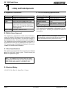
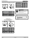
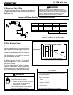
D. Pipe Selection Chart
The table below can help you calculate the equivalent feet
of pipe which is a method used to determine pellet vent size.
See Figure 11.1
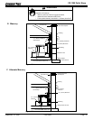
C. Equivalent Feet of Pipe
2 ft.
2 ft.
ft.
2 ft.
Example of 3 Elbow-Rear Vent Termination Calculaton
Figure 11.1
Figure 11.2
Pellet Venting
Component
# of
Elbows
Feet of
Pipe
Multipled
By
Equivalent
Feet
Components
Equivalent Feet
90
o
Elbow or Tee
X 5 15
45
o
Elbow
X 3
Horizontal Pipe
7 X 1 7
Vertical Pipe
2 X 0.5 1
Total Equivalent Feet 23
Note: This is a generic example and is not
intended to represent any specic fuel type.
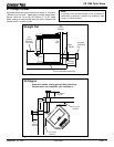
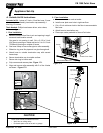
Fire Risk.
Do NOT pack insulation or other
combustibles between restops.
• ALWAYS maintain specied clearances
around venting and restop systems.
• Install restops as specied.
Failure to keep insulation or other material
away from vent pipe may cause re.
WARNING
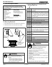
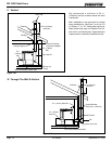
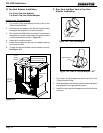
CAUTION
Follow Chimney Connector Manufacturer’s Instructions
for Proper Installation.
ONLY use connector:
• Within the room, between appliance and ceiling or
wall.
Connector shall NOT pass through:
• Attic or roof space
• Closet or similar concealed space
• Floor or ceiling
Maintain minimum clearances to combustibles.