


35
12.0 CHANGING COMPONENTS
Publication No. 5111811
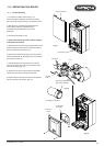
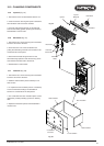
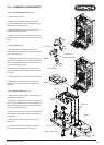
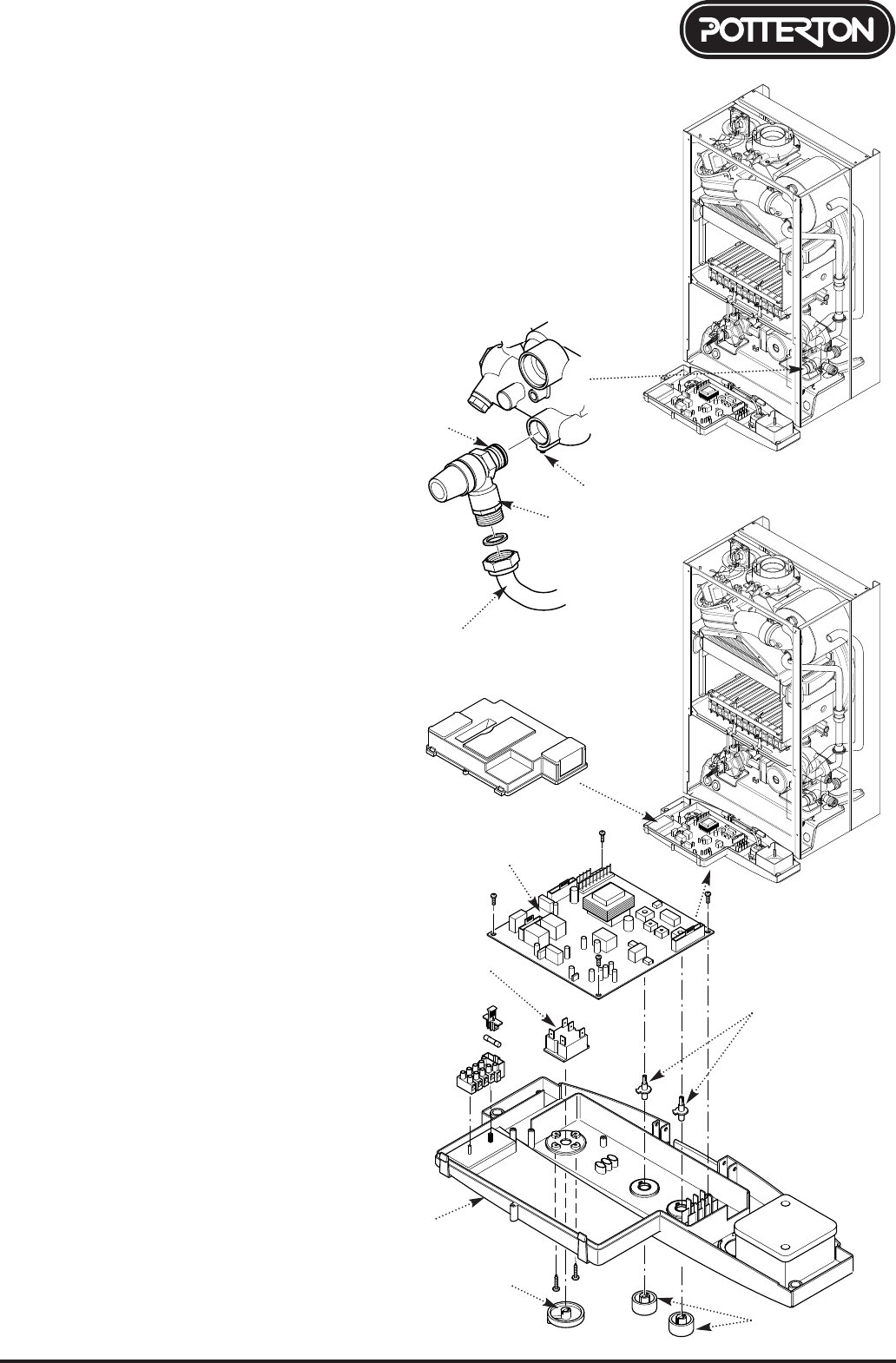
12.17 Pressure Relief Valve (Fig. 65)
1. Drain the primary circuit.
2. Disconnect the discharge pipe from the valve.
Using a suitable hexagon key undo the grub screw
sufficiently to release the valve.
3. Note the orientation of the valve, rotate it and
withdraw it from the manifold.
4. Fit the new valve and ‘O’ ring seal and set to the
previously noted orientation. Reassemble in reverse
order.
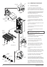
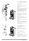
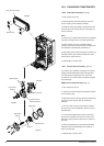
12.18 P.C.B. (Fig. 67)
1. Note the settings of the temperature control
knobs. Rotate the knobs fully anticlockwise and pull
them off the drive pins.
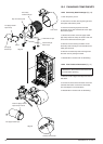
2. Completely undo the screws securing the control
box cover and release the cover retaining barbs from
their slots. Disengage the rear of the cover from the
control box hinge pin (Fig. 66).
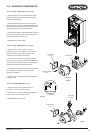
3. Note the position of all plugs and wires on the
P.C.B. and disconnect them. Pull the drive pins off
the P.C.B.
4. Undo the securing screws and remove the P.C.B.
5. Reassemble in reverse order, ensuring that the
temperature controllers are reset to their previous
positions.
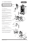
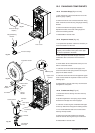
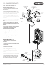
12.19 Selector Switch (Fig. 67)
1. Note the setting of the selector switch knob and
carefully pull it off the facia.
2. Completely undo the screws securing the control
box cover and release the cover retaining barbs from
their slots. Disengage the rear of the cover from the
control box hinge pin (Fig. 66).
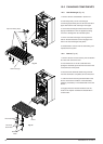
3. Note the position of the electrical connections and
the orientation of the switch. Remove the electrical
connections.
4. Remove the screws securing the switch to the
facia panel.
5. Fit the new switch, ensuring that it is correctly
positioned and reassemble in reverse order.
Pressure Relief Valve
Grub Screw
‘O’ ring seal
Discharge Pipe
Control Box Cover
P.C.B.
Selector
Switch
Facia
Selector Switch Knob
Temperature Control
Knobs
Fig. 65
Fig. 66
Fig. 67
Drive Pins