


31
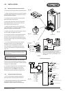
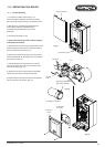
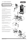
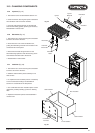
12.0 CHANGING COMPONENTS
Publication No. 5111811
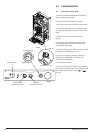
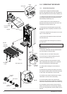
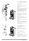
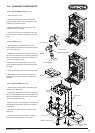
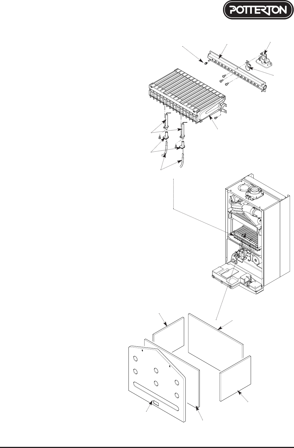
12.5 Injectors (Fig. 54)
1. Remove the burner as described in Section 12.4.
2. Undo the screws securing the injector manifold to
the inlet elbow and remove the manifold.
3. Unscrew and replace injectors as required and
examine the sealing gasket, replacing as necessary.
Reassemble in reverse order.
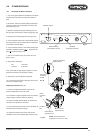
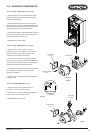
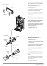
12.6 Electrodes (Fig. 54)
1. Remove the four screws securing the combustion
box door and remove the door.
2. Draw the burner out of the combustion box,
pulling the electrode grommets from the slots in the
combustion box lower panel.
3. Disconnect the lead and grommet from the
electrode being replaced. Undo the securing screw
and withdraw the electrode to the burner.
4. Reassemble in reverse order.
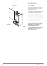
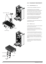
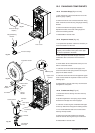
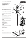
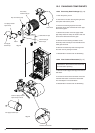
12.7 Insulation (Fig. 55)
1. Remove the four screws securing the combustion
box door and remove the door.
2. Slide the side insulation pieces carefully out of
their carriers.
3. To replace the rear insulation piece it is necessary
to remove the heat exchanger as described in
Section 12.3 and slide out the side pieces.
4. The combustion box door insulation piece can be
replaced by carefully bending up the two retaining
tabs.
5. Replace all insulation pieces and reassemble in
reverse order.
13.8
Injector
Manifold
Inlet Elbow
Gasket
Injector
Burner
Electrode
Grommets
Electrode
Leads
Side Insulation
Rear Insulation
Front Insulation
Combustion
Box Door
Side Insulation
Electrodes
Fig. 54
Fig. 55