


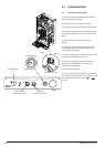
8.0 INSTALLATION
20
Publication No. 5111811
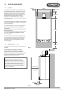
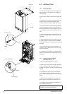
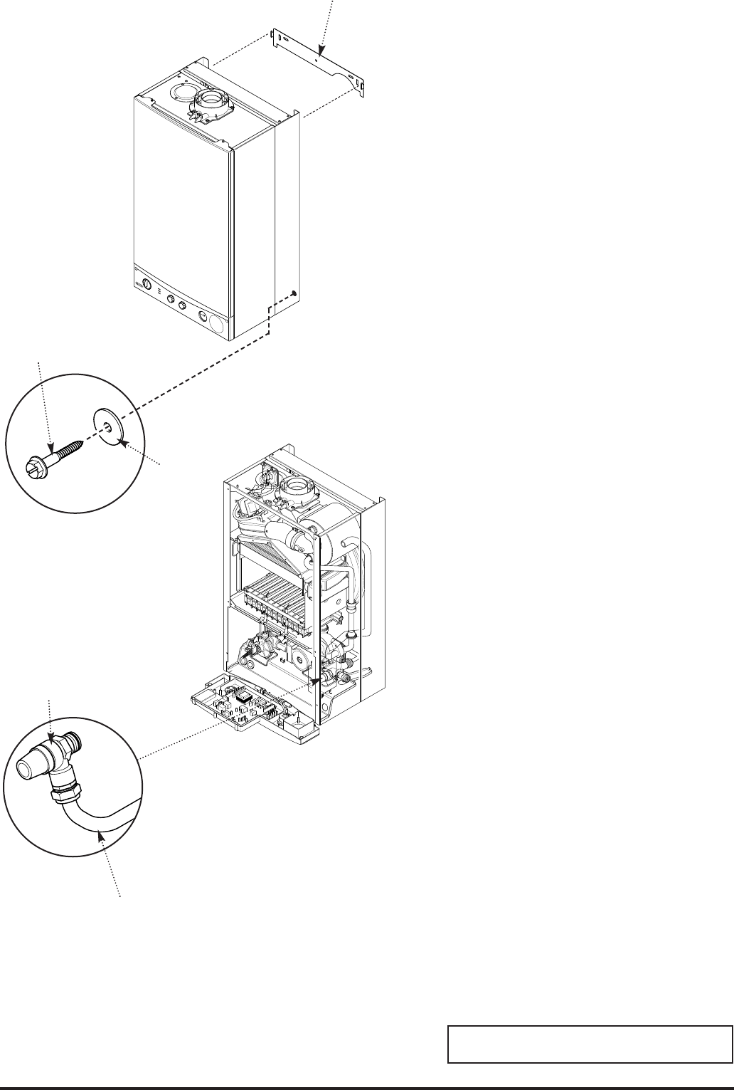
8.4 Fitting The Boiler
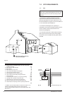
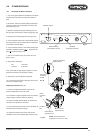
1. Lift the boiler using the lower edges. Engage the
slots at the top rear of the boiler on the wall plate
hooks (Fig. 20).
2. Ensure that the boiler is level and sits against the
wall.
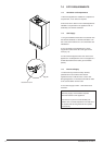
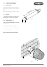
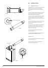
3. Take the two steel washers and remaining screws.
Using the previously drilled and plugged holes,
secure the bottom of the boiler to the wall (Fig. 21).
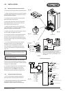
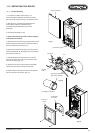
4. Remove the elbows, valves and sealing washers
from the packaging. The 3/4 in valve with internal
filter must be fitted to the central heating return. The
filter is visible through the branch connection of the
valve.
5. Using the sealing washers provided connect the
valves to the heating flow and return, and the cold
water inlet.
6. Connect the elbows to the gas service cock and
hot water outlet pipe, and then connect the elbows
to the boiler. Connect the elbows with flared ends to
the valves.
7. Ensure that the sealing washers are used on all
connections. The rubber washers must be used on
the gas connections.
8. The gas and water supplies, central heating flow
and return and domestic hot water flow can now be
connected.
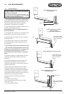
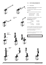
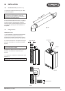
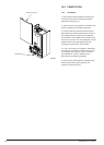
8.5 Fitting the Pressure Relief
Discharge Pipe (Fig. 22)
1. Remove the discharge pipe from the kit.
2. Determine the routing of the discharge pipe in the
vicinity of the boiler. Make up as much of the
pipework as is practical, including the discharge pipe
supplied.
3. The pipework must be at least 15mm diameter
and run continuously downwards to a discharge
point outside the building. See section 6.7 for further
details.
4. Using one of the sealing washers, connect the
discharge pipe to the adaptor and tighten the nut.
5. Complete the discharge pipework and route it to
the outside discharge point.
IMPORTANT: Make all soldered joints before
connecting to the pressure relief valve.
Fig. 22
Fig. 20
Fig. 21
Pressure Relief Valve
Securing Screw
Washer
Wall Plate
Discharge Pipe