


11.0 SERVICING THE BOILER
28
Publication No. 5111811
11.1 Annual Servicing (Cont)
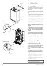
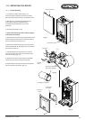
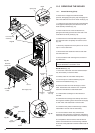
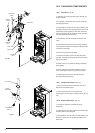
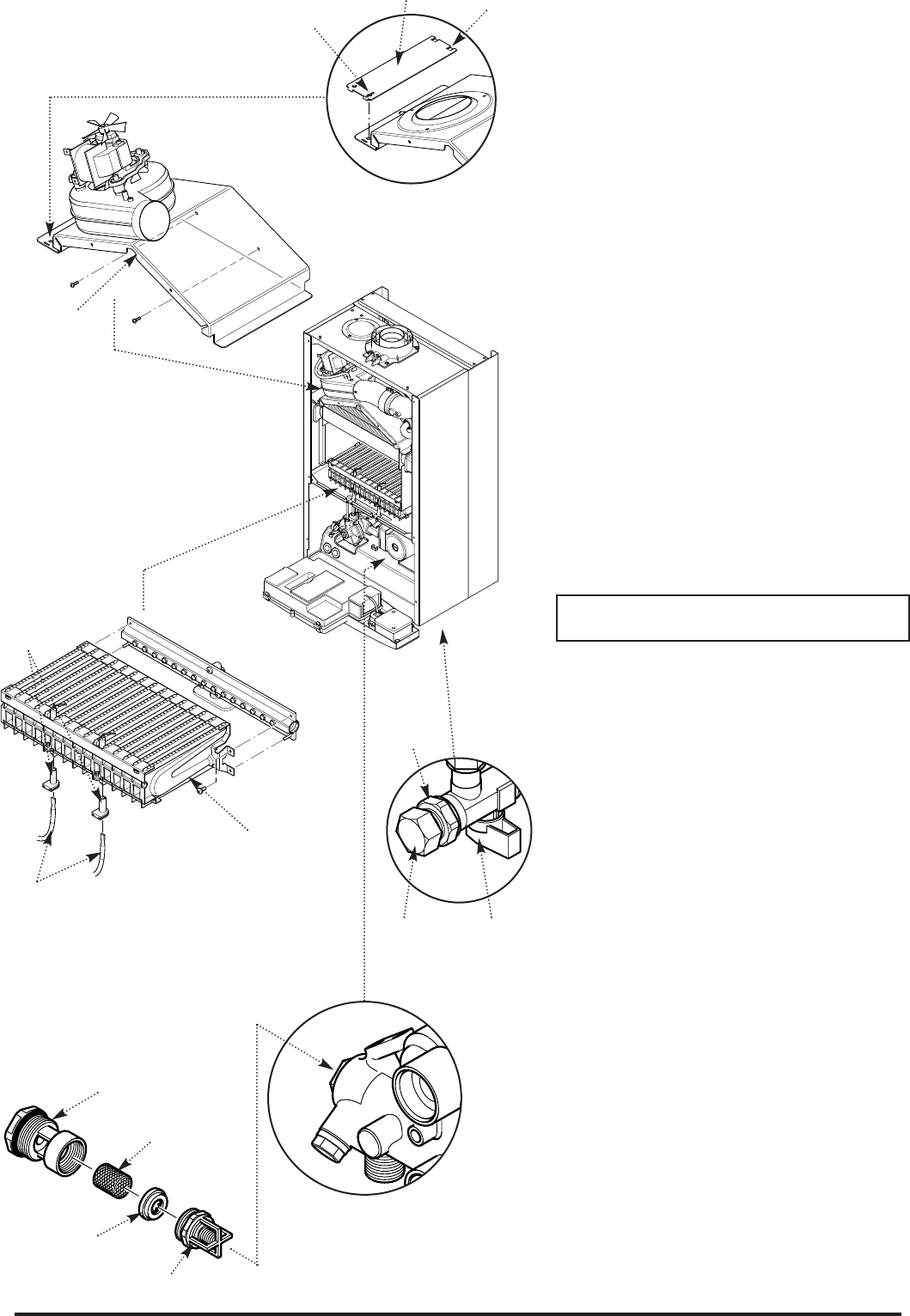
10. Ease the front edge of the left hand baffle
upwards, disengaging the spring clip. Disengage the
tab on the baffle from the slot in the fan hood (Fig.44).
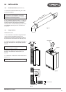
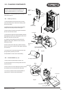
11. Undo the screws securing the fan hood assembly
to the appliance back panel, and draw the fan and
hood assembly forwards (Fig. 45).
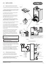
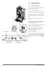
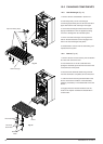
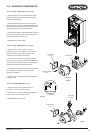
12. Draw the burner out of the combustion box,
pulling the electrode grommets from the slots in the
combustion box lower panel (Fig. 46).
13. Disconnect the electrode leads and grommets
from the electrodes. Completely remove the burner
(Fig. 46).
14. Brush any deposits from the injectors. Do not use
a pin or wire to clean them.
15. Brush the burner blades and venturis and clean
the combustion box.
16. Ensure that the heat exchanger fins are clear of
any obstruction.
NOTE: If necessary the secondary heat exchanger
may be dismantled - see section 12.23
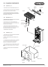
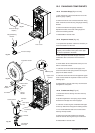
D.H.W. Filters (Fig. 48)
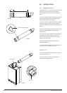
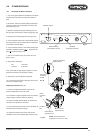
17. If the flow of domestic hot water is diminished, it
may be necessary to clean the filters.
18. Initially check the cold water inlet tap filter.
19. Turn the tap off. Undo the blanking cap and
remove the threaded bush (Fig. 47).
20. Extract the filter and rinse thoroughly in clean
water. Reassemble and check the flow. If required
clean the manifold filter as described below.
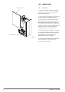
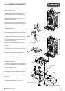
21. Undo the filter cartridge from the inlet/return
manifold.
22. Dismantle the cartridge and carefully remove the
flow regulator and filter gauze. Rinse them thoroughly
in clean water and reassemble in reverse order.
23. Check that the pressure vessel charge is 0.5bar,
reassemble in reverse order of dismantling.
24. Turn the selector switch fully anticlockwise
against the spring pressure to position R and hold for
2 seconds to reset the boiler before recommissioning.
25. Complete the relevant Service Interval Record
section of the Benchmark Commissioning Checklist
at the rear of this publication and then hand it back to
the user.
Burner
Electrode
Grommets
Electrode
Leads
Inlet / Return Manifold
Cartridge
Body
Filter Gauze
Flow
Regulator
Venturi
Gas Supply Pipe
Blanking
Cap
Cold Water
Inlet Tap
Threaded
Bush
Fig. 46
Fig. 55
Fig. 48
Fig. 47
Spring Clip
Fan and Hood
Assembly
Baffle
Tab
Fig. 44
Fig. 45