


12.0 CHANGING COMPONENTS
32
Publication No. 5111811
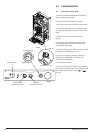
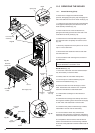
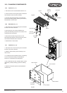
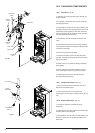
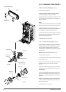
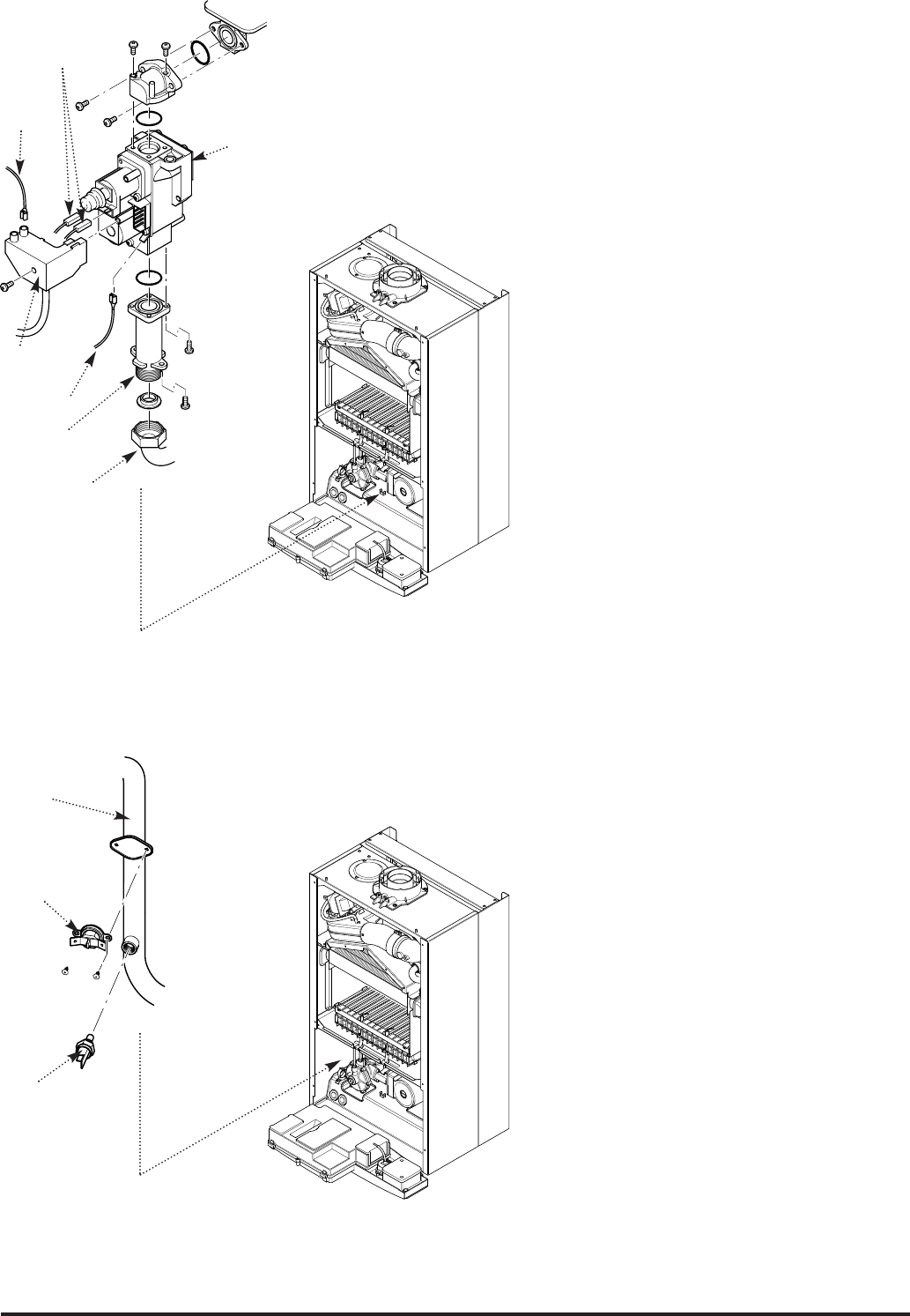
12.8 Gas Valve (Fig. 56)
1. Undo the nut on the gas feed pipe at the tap rail
under the boiler.
2. Completely undo the securing screws and hinge
the facia panel down.
3. Disconnect the wires from the valve modulator and
the ignition lead from the spark generator. Disconnect
the pressure sensing pipe from the valve. Undo the
screw securing the spark generator electrical plug to
the valve and disconnect the plug.
4. Pull the earth wire off the spade terminal on the
valve.
5. Remove the screws securing the inlet pipe flange
to the tap rail and those securing the outlet manifold
to the burner manifold.
6. Remove the valve from the boiler.
7. Note the orientation of the inlet pipe and outlet
manifold. Undo the securing screws and remove the
pipe and manifold.
8. Examine the ‘O’ ring seals for damage, replacing
as necessary.
9. Fit the inlet pipe and outlet manifold to the new
valve, ensuring that the ‘O’ ring seals are in place.
10. Reassemble in reverse order and check the
burner pressure (Section 9.2).
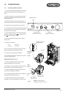
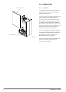
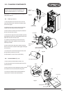
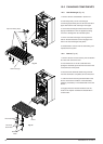
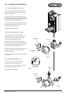
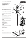
12.9 Temperature Sensor (Fig. 57)
1. Ease the retaining tab on the sensor away and
disconnect the electrical plug.
2. Unscrew the sensor from it’s pocket and
reassemble in reverse order. The plug will only fit one
way.
12.10 Safety Thermostat (Fig. 57)
1. Pull the two electrical connections off the
thermostat.
2. Remove the screws securing the thermostat to the
mounting plate on the flow pipe.
3. Reassemble in reverse order. The thermostat is not
polarised - either wire can fit either terminal on the
thermostat.
Gas Valve
Inlet Pipe
Gas Feed
Pipe
Electrical
Plug
Temperature
Sensor
Safety
Thermostat
Flow Pipe
Fig. 56
Fig. 57
Modulator
Wires
Ignition
Lead
Earth Wire