


Electromagnetic interference
Discharge lamps do not only emit visible radiation, they also generate
radio-frequency energy in the radio spectrum.This can cause disturbance
of the operation of electronic equipment such as computer keyboards,
television or radio receivers, hence the name radio interference.
As the luminaires in which the lamps are used should fulfil international
requirements such as EN 55015 (CISPR 15), the radio interference in
practice is sufficiently low to have no harmful effects on the surrounding.
Products with the mark conform to VDE 875 part 1.
The generation of radio-interference radiation is normally caused by
lamp electrode oscillations.It has a broad-band character,usually with
frequencies of up to 1500 kHz, so FM and television receivers are not
affected.
The electromagnetic waves, which can have effects on the AM broadcast
band, are propagated in two ways: either directly through the mains into
the receiver,or via radiation picked up by the aerial.
The latter form of interference will seldom occur with discharge lamps,
as the ballast will suppress the broad-band signals.The radiation
produced by the lamp will nearly always remain below the threshold
value at which interference takes place, especially where the lamp is
at some distance from the aerial (more than, say, 1 metre).
The supply cables can emit interference radiation when they are not
buried in the ground or laid in earthed steel piping, which is the best
screening against interference. However, it sometimes happens that an
interference signal reaches the receiver by way of its mains input.The
interference signal can consist of high-frequency harmonics of the mains
frequency or high amplitude pulses.The former are generally adequately
suppressed in the ballast. Experience has shown that interference may
be caused by fluorescent luminaires with external ballast where the
radiation from the supply wires is picked up by telephone or other cables.
If external ballasts are used, the supply cables between ballast and
luminaire should be as short as possible. Ballast coils should be split
into two adjacent parts (split-windings type of ballast). In case of Class
I luminaires the supply wires should be shielded and this shielding
should be properly connected to the earth connection.
In practically all other cases it will be necessary to connect a delta filter
between the mains supply and the input to the lamp circuit.
310
5
131
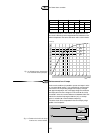
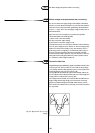
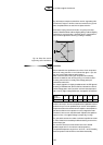
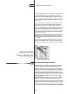
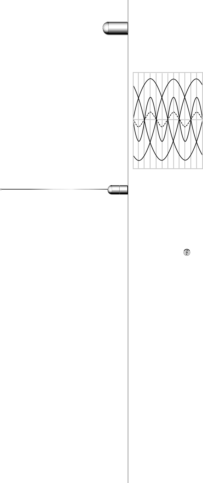
Fig. 125. Fundamental and third
harmonic in a three-phase mains. R, S
and T are the fundamentals in the three
conductors. Owing to the phase shift,
this results in a zero current in the
neutral lead.
a) Third harmonic of a phase,
b) Third harmonic of all three phases in
the neutral lead.The individual currents
reinforce each other.
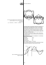
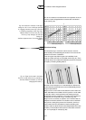
3.9 Harmonic distortion
RST
(b)
(a)
0
60
120
180
240
300
360