


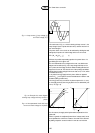
Another value marked on the ballast is the coil temperature rise ∆t.
This is the difference between the absolute coil temperature and the
ambient temperature in standard conditions and is measured by a
method specified in IEC Publ. 920 (EN 60920). Common values for ∆t
are from 50 to 70 degrees in steps of 5 degrees.
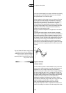
The coil temperature rise is measured by measuring the ohmic
resistance of the cold and warm copper coil and using the formula:
∆t = {(R
2
- R
1
)/R
1
} . (234.5 + t
1
) - (t
2
- t
1
)
or: t
c
= R2/R1 . (t
1
+ 234.5) - 234.5 (IEC 598-1 Appendix E)
where R
1
= initial cold coil resistance in ohm
R
2
= warm coil resistance in ohm
t
2
= ambient temperature at measuring R
2
in Celsius
t
1
= initial ambient temperature at measuring R
1
in Celsius
t
c
= calculated warm coil temperature in Celsius
∆t= t
c
- t
2
in Kelvin
The value 234.5 applies to copper wire; in case of aluminium
wire, the value 229 should be used.
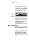
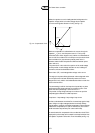
So a ballast marked with t
w
130 and ∆t 70, will have the specified 10
years average life in continuous operation at standard conditions at an
ambient temperature of 130 - 70 = 60 ºC.When the ambient
temperature around the ballast is higher,a shorter ballast life has to
be accepted or sufficient air circulation or cooling has to be applied.
The so-called ambient temperature mentioned in this chapter is not
the room or outside temperature, but the temperature of the micro-
environment of the ballast. Built into a luminaire or ballast box the air
temperature around the ballast is higher than the outside ambient
temperature.This higher temperature has to be added to the coil
temperature rise ∆t to find the absolute coil temperature:t
c
= t
2
+ ∆t.
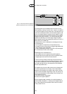
Additionally, a third temperature figure can be mentioned on the ballast:
the ballast temperature rise in abnormal conditions, again measured
according to specifications like EN 60920. In short: it is the winding
temperature rise at 110 per cent mains voltage when the glow-switch
starter,belonging to the system, is short-circuited.
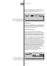
The marking of the three temperature markings should be :
∆t ** / *** / t
w
*** with * = figure
Example: ∆t 70 / 140 / t
w
130.
Watt losses
Ballast losses normally are published as ‘cold’ values, meaning that the
ballast is not energised or only very shortly before and the ballast
winding is at ambient temperature (25 ºC). In practice the ballast will
reach more or less the marked ∆t value and then the copper resistance
is approx. 25 per cent higher than in the ‘cold’ situation.Therefore the
‘warm’ losses in practice will be 10 - 30 per cent higher than the
published values.
17
5
112
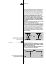
1.6 Maximum coil temperature t
w
and ∆T