


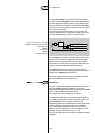
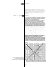
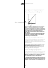
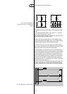
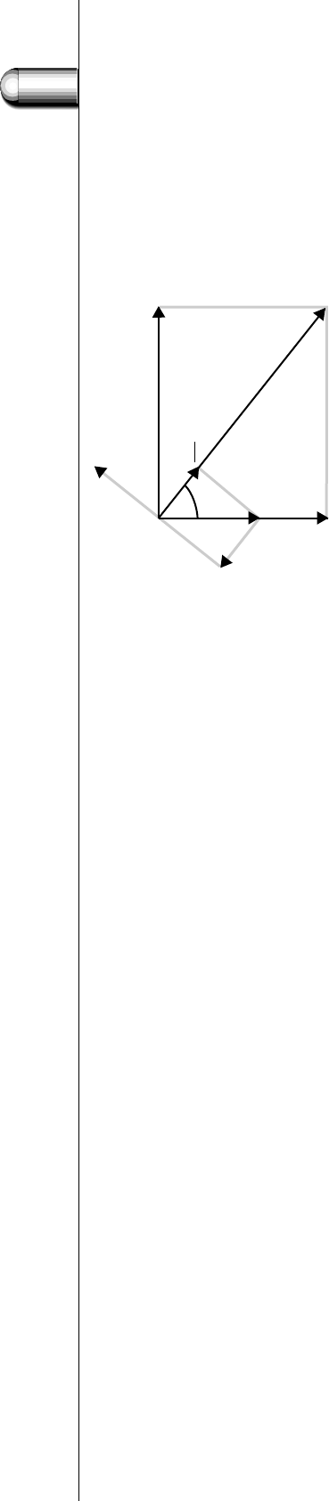
ballast, the capacitor current is leading 90 electrical degrees to the
capacitor voltage (which is the mains voltage). So the capacitor
current has the opposite direction of I
l
sin ϕ (see Fig. 114).
Maximum compensation is achieved when the current through the
capacitor I
c
= I
l
sin ϕ ; then the power factor is 1.This is purely
theoretical, as the vector diagram is only valid for the fundamentals of
the currents. Due to distortion in the lamp current (see section 5.3.9:
Harmonic distortion), the maximum practical power factor is
between 0.95 and 0.98.This explains the difference between power
factor and cos ϕ.
The power factor is the result of the quotient of the actual wattage
and the product of mains voltage and mains current, including the
harmonics, and can be calculated as follows:
Power factor (P.F.) = total wattage/mains voltage . mains current
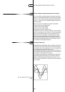
The angle ϕ is the phase shift angle between mains voltage and mains
current and can be found and calculated by means of the vector
diagram.This is only valid for the fundamentals and does not take into
account the harmonics.
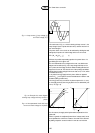
The same analogy is valid for the lamp: there is practically no phase
shift between lamp voltage and lamp current: both are zero at the
same time. So the phase angle α is zero and cos α = 1.
The product of lamp voltage and lamp current does not equal the
lamp wattage; the difference is called lamp factor:
Lamp factor = lamp wattage / lamp voltage . lamp current
and has a value between 0.8 and 0.9. For the same lamp type the lamp
factor is higher for higher wattages, identical to the lamp efficacy.
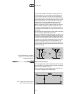
Typical capacitor values for this parallel compensation (also sometimes
called mono-compensation) for a 50 Hz mains are 4.5 µF for a 36 or
40 W fluorescent lamp and 6.5 µF for a 58 or 65 W lamp.
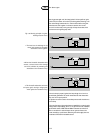
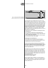
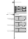
A second method for compensation is the so-called duo-circuit.This is
employed for pairs of lamps, as for example in two-lamp luminaires. Here
the capacitor is placed in series with one of the ballasts (see Fig. 115).
5
121
Fig. 114. Compensated circuit.
3.4 Power factor correction
V
b
V
m
V
l
I
l
I
l
sin ϕ
I
cap
I
l
cos ϕ
ϕ