


There are other advantages to be gained from employing filter coils.
The parallel capacitor can cause troublesome switching phenomena
to occur, which can give rise to very large current surges.Although
these surges are of only very short duration (a few milliseconds),they
are nevertheless sufficient to cause switching relays to stick or circuit
breakers to switch off.The filter coil serves to prevent this problem
by damping the very short, high amplitude pulses in the current.
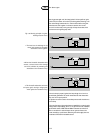
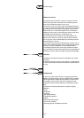
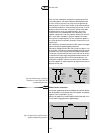
The type of filter coil needed depends on the capacitance of the
capacitor employed. So, in fact every capacitor needs its own filter coil.
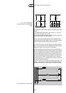
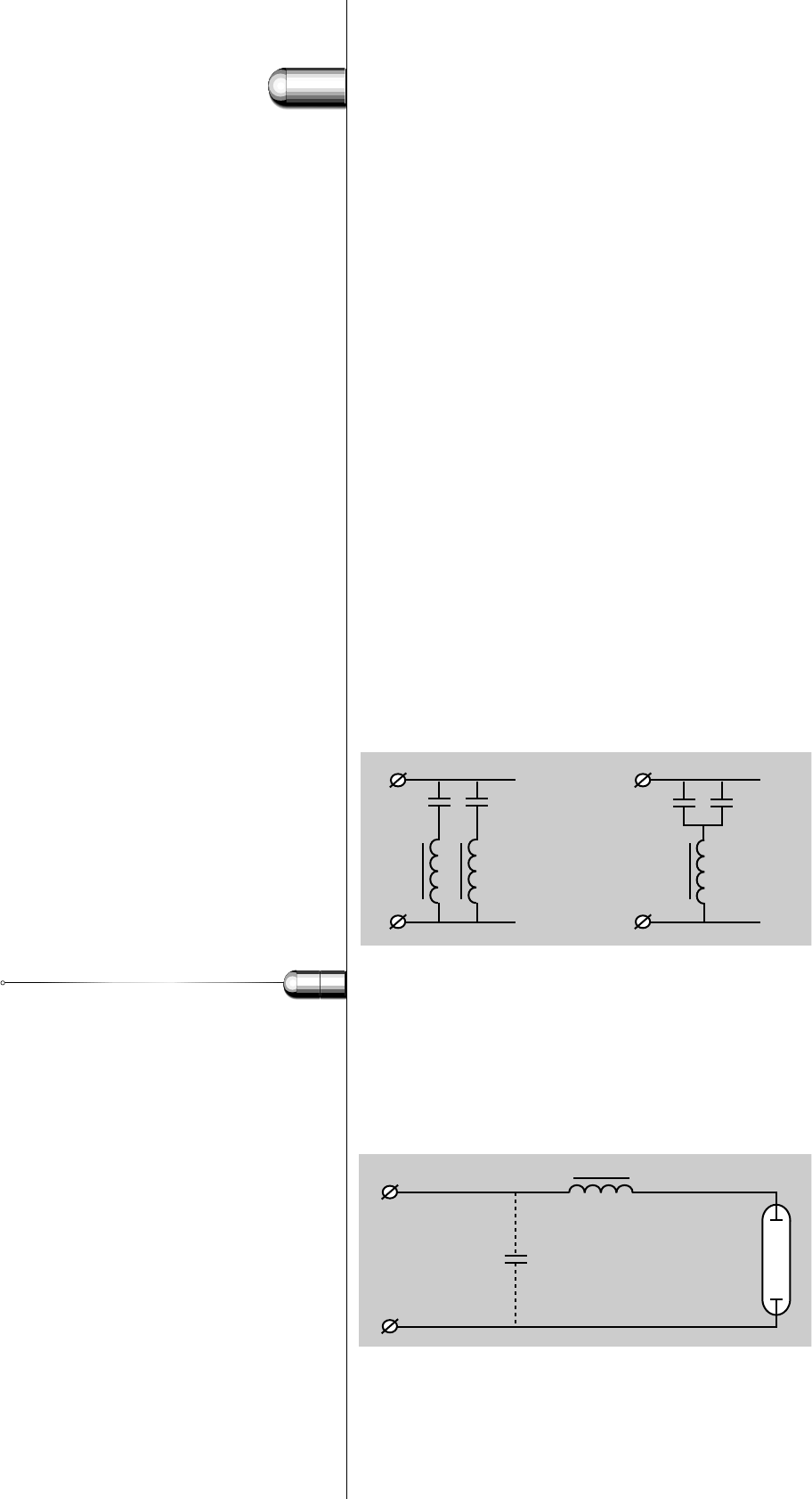
But in some cases it is possible to group the capacitors and match
them with the corresponding filter coil. For example: two capacitors
of 4 µF parallel can be connected in series with one filter coil for 8 µF
(see Fig. 109).
Also central filter coil systems exist where a filter system in the supply
system is blocking the applied signalling frequencies.
Although the voltage across the filter coils is rather low (approx. 14 to
20 V), the filter coils have to be regarded as ballasts, as they are directly
connected to the mains.They also cause some additional watt losses.
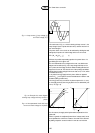
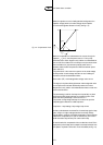
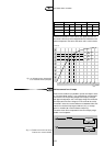
The amount of third and fifth harmonics in the mains current will rise
in cases where the mains supply voltage is disturbed with third or fifth
harmonics, when applying a filter coil.The total impedance for the
combination of capacitor and filter coil is lower than the impedance
of the sole capacitor for these frequencies (see section 5.3.9: Harmonic
distortion and Fig. 108).
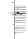
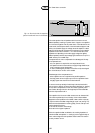
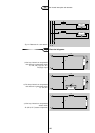
Power factor correction
Circuits with gas-discharge lamps are stabilised with inductive ballasts
and compensated for a good power factor with a parallel compensating
capacitor (mono-compensation, Fig. 110).
Without the capacitor the inductive ballast causes a phase shift of the
current, which is lagging behind the applied voltage.
34
5
119
Fig. 109. Different ways of grouping
capacitors to match them with the
corresponding filter coil.
Fig. 110. Power factor correction with a
parallel compensating capacitor.
3.3 Filter coils
L
N
L
N
2 x 4 µF
coils
2 x 4 µF
capacitors
=
1 x 8 µF
filter coil
4 x 4 µF
capacitors
B
C
La
L
N