


If the mains current is about half the lamp current, the capacitor is
in order, resulting in a power factor of approx.0.9.
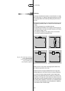
2) Disconnect capacitor from circuit and discharge by short-circuiting
terminals.
Check capacitor with ohmmeter set at highest resistance scale.
If the meter indicates a very low resistance which then gradually
increases, the capacitor is in order.
If the meter indicates a very high resistance which does not diminish,
the capacitor is open-circuit and should be replaced.
If the meter indicates a very low resistance which does not increase,
the capacitor is short-circuited and should be replaced.
This method can also be used for the series capacitors.
Measurement of the starting pulse voltage of a starter is beyond the
capability of most instruments available in the field, due to the high
peak voltages.The practical way is to replace the suspect starter by
another one.
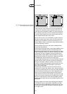
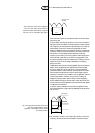
Measurements on the ballast can be done in two steps after
disconnecting the ballast from the circuit:
1) Check with ohmmeter on the terminals.Values should be low (15 to
200 Ω, depending on lamp power). If the value is high, the ballast is
open-circuit.
2) Connect ballast on the mains supply (well fused!) and measure the
short-circuit current.This should be approx. 1.5 times the nominal
lamp current.
Measurements of the lamp electrodes can be done at the 4-pin
versions with a standard ohmmeter.The resistance of the electrodes
varies for the different lamp types, but is less than 50 Ω when cooled
down.
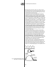
Measurements on the lamp in operation can only be done if the starter
is not operative.As the lamp voltage is not a sine wave and subject to
the tolerances in the total circuit,measured lamp voltages only give a
rough indication of correct functioning.The lamp current can be
measured rather accurately.
Measurements of the mains supply normally involve the effective value
of the supply voltage and mains current and sometimes the frequency.
When pulses, interruptions, harmonics (wave form) can play a role,
‘laboratory’ instruments are necessary,preferably during a longer period
while storing or noting the readings.
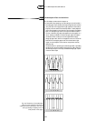
It is advisable to measure the various phase currents in an installation,
in order to check the balance of the load.Also the measurement of
the current in the neutral in a star network gives an indication of the
quality of the total system. Due to harmonics in the lamp current, the
current in the neutral is not zero, but should be 50....70 per cent of
the phase currents. If the current in the neutral is higher than in the
phases, the balance in the load is not correct or the mains supply
waveform does not have a good sine wave.This can lead to overload
of the neutral cable.
5
152
3.19 Fault finding