


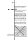
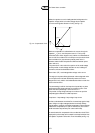
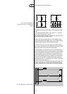
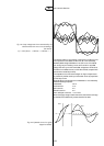
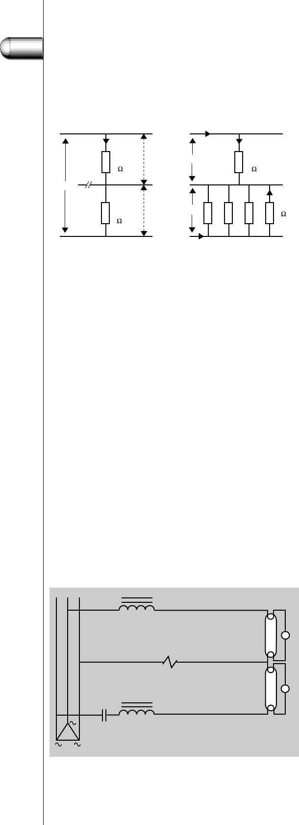
This makes 1000 + 250 = 1250 Ω. So the current will be 400 / 1250 =
0.32 A.
The voltage across R1 will be 0.32 . 1000 = 320 V (V = I . R), so the
power in R1 will be 320 . 0.32 = 102 W.
The voltage across the four parallel resistors is 0.32 . 250 = 80 V, so the
power in each resistor is 80 . 0.08 = 6.4 W.
Now it is seen that the smaller load (R1) is overloaded by a higher
voltage (320 instead of 230 V) and a higher current (0.32 A instead of
0.23 A).The higher load (R2 to R5) is greatly underloaded.
In practice the circuits are not that simple,but the essential aspect is
that in case of a floating neutral the smallest load will receive a higher
voltage and a higher current and so will be overloaded.
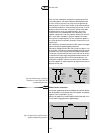
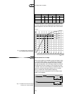
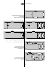
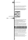
A second possibility of resonance has to do with the employment of
inductive and capacitive circuits in the same installation. In the capacitive
circuit,the impedance of the capacitor is twice the impedance of the
inductive ballast. So when an inductive and a capacitive circuit get in
series, the total impedance will be zero, resulting in an unlimited current
(resonance).This can happen in a delta-network when one phase is
interrupted (Fig.120) or in a star-network with common neutral when
the neutral is interrupted (Fig. 121).
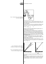
Resonance problems can be prevented with special switch gear.If the
neutral in a star-network or a phase in the delta-network fails, such
special gear switches off the overall supply for the lighting installation.
5
125
Fig. 119.The consequences of
interrupted neutral in a phase/neutral
network.
Fig. 120. Resonance in a delta-network.
3.6 Neutral interruption and resonance
L
1
L
2
I
total
1000
250
400V
V
1
V
2
L
1
N
L
2
I
R
I
R
4 I
R
I
R
1000
1000
each
230V
230V
R
1
R
2
R
3
R
4
R
5
B
B
‘TL’D
‘TL’D
C
S
S