


The series capacitor has an impedance which is twice the normal
ballast impedance, resulting in a power factor of approx. 0.5 capacitive
for one branch.Together with the power factor of 0.5 inductive for the
other branch, the total power factor of the two branches is approx.0.95.
With a normal 230 V supply, the voltage across the capacitor is about
400 V.To fulfil all relevant requirements,the tolerance on the capacitor
capacitance value has to be within +/- 4 %.The nominal value of the
capacitance is depending on the mains supply voltage, the applied
ballast impedance and the lamp wattage.Typical values are 3.4 µF for a
36 W and 5.3 µF for a 58 W lamp.
Compared with the mono-compensation the advantages of this way
of compensation are:
- only one capacitor is required for two lamps, instead of two,
- the capacitive branch is less sensitive to supply voltage deviations, as
it has a constant current characteristic,
- in case of actadis signals (see section 5.3.3: Filter coils) these signals
are not influenced, so no filter coil is needed.
Disadvantages of duo-compensation are:
- series capacitors are more expensive than parallel capacitors,
- the lamp power and so the light output from the capacitive branch
is slightly higher than that from the inductive branch.
In some countries, practically all multi-lamp luminaires have built-in
duo-circuits for each pair of lamps (also called a ‘dual-lamp’ or ‘lead-lag’
circuit).Mono-compensation, on the other hand, is generally left to
the installer, although there are also single-lamp luminaires available
with the compensation built in.
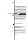
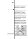
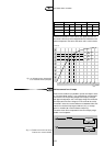
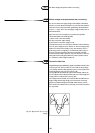
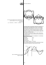
The capacitive circuit has a so-called ‘constant current characteristic’.
This can be explained by the non-linearity of the inductive ballast.
Suppose that the impedance of the ballast is 400 Ω, which varies, say
10 per cent when the ballast voltage changes 10 per cent (see Fig.116).
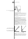
With the inductive ballast the resulting (lamp) current at 90 per cent
mains voltage will be lower:
A: as result of the lower mains voltage,
B: as result of the higher impedance.
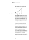
With the capacitive ballast combination, the resulting impedance of
inductive ballast and capacitor is reacting in just the opposite way: at
lower mains voltage the total impedance is also lower.This results in
a nearly constant current.
5
122
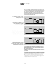
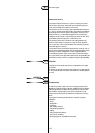
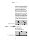
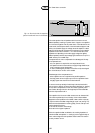
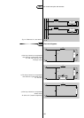
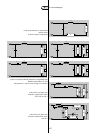
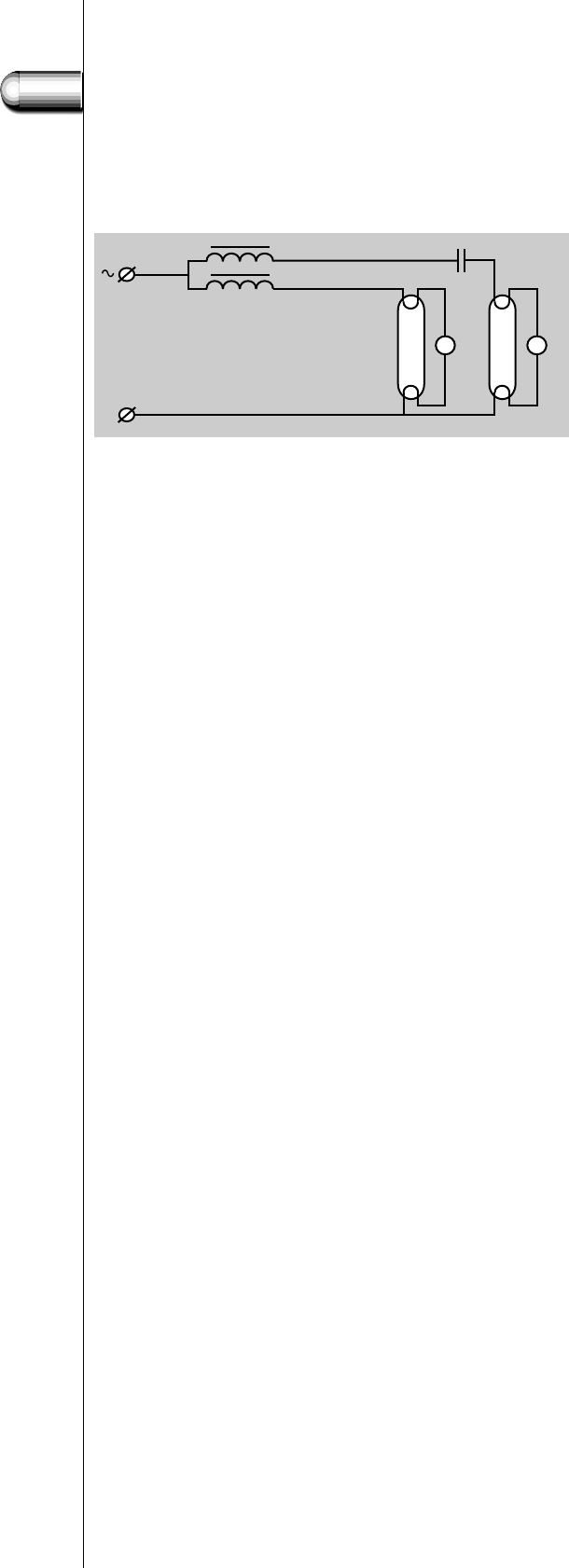
Fig. 115. Duo-circuit with the capacitor
placed in series with one of the ballasts.
3.4 Power factor correction
0
‘TL’
1
‘TL’
2
SS
L2
L1
C