


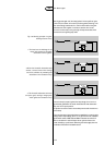
Capacitors for lighting applications must have a discharge resistor
connected across the terminals to ensure that the capacitor voltage is
less than 50 V within 1 minute after switching off the mains power. In
special cases the voltage level must be 35 V within 1 second, see
IEC 598-8.2.7.
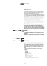
Filter coils
In some countries, including Belgium, the Netherlands and France, the
electric distribution network is used for transmitting messages under
responsibility of the local energy supply authority.
Signals are sent over the electricity supply network for a number of
purposes: to switch road lighting, to call up fire brigades and the
police, to switch night-tariff kWh-meters, and so on. It is important,
therefore, that this signalling system is not disturbed, which may occur
when parallel power factor correction capacitors for lamp circuits are
employed. Capacitors present a low reactance to the 200-1600 Hz
signals employed for signalling, with the result that these are in danger
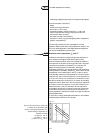
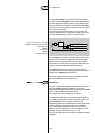
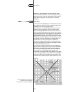
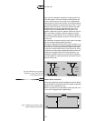
of being short-circuited in a capacitive circuit.To avoid this, a coil must
be connected in series with the capacitor connected parallel to the
mains.This filter coil, as it is termed, presents a reactance that
increases with rising signal frequency.The coil reactance is therefore
chosen such as to balance out the reactance of the capacitor at 200 Hz
(the resonance frequency, see Fig. 108).
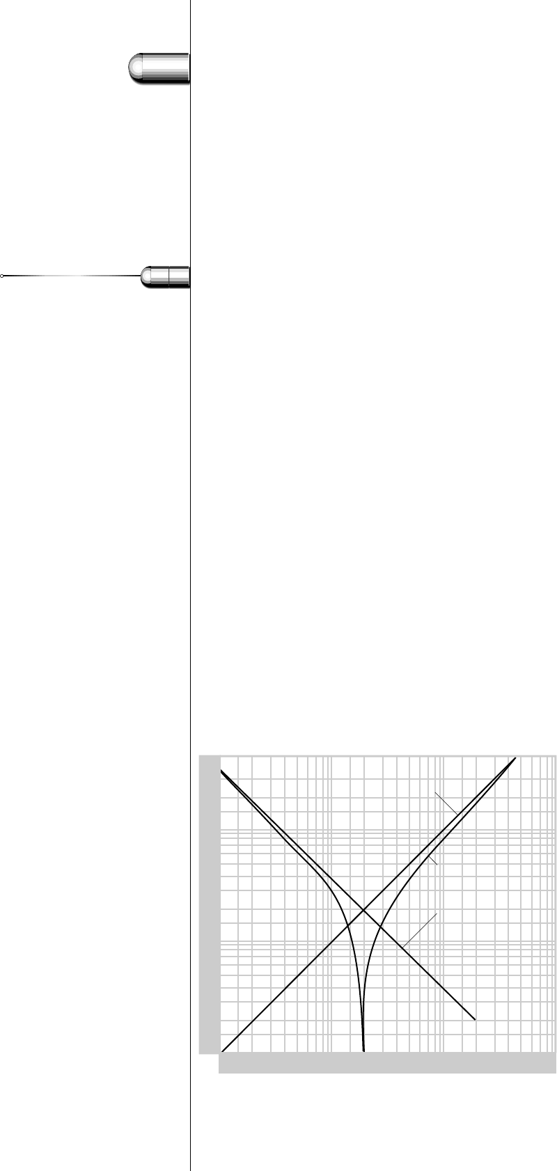
For currents with a frequency of 50 Hz the circuit is predominantly
capacitive,which is necessary for power factor correction.Above 200 Hz
the circuit becomes predominantly inductive, which is necessary for
the blocking of audio-frequency signals.At 200 Hz the impedance is
only formed by the ohmic resistance, mainly of the filter coil.
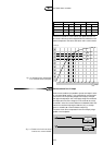
As can be seen from the graph, the filter coil is effective for audio signals
of 300 Hz and higher, because then the impedance of the coil/capacitor
combination is higher than the impedance of the sole capacitor. Filter
coils should not be used when the audio signals are 300 HZ or lower.
33
5
118
Fig. 108. Impedance of a filter coil, a
capacitor and a coil/capacitor
combination as a function of frequency.
3.2 Capacitors
impedance (Z)
frequency(Hz)
capacitive inductive
2
4
6
8
10
2
2
4
6
8
10
3
10
1
2
4
6
8
10
2
2
4
6
8
10
3
2
4
6
8
10
4
10
1
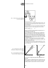
impedance of filtercoil
Z = ωL
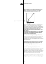
impedance of coil
and capacitor
Z =
|
ωL -1
|
impedance of capacitor
Z = 1
___
ωC
___
ωC