


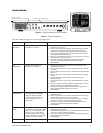
8 Pelco Manual C1968M-A (1/02)
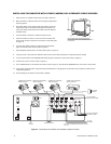
INSTALLING THE MONITOR WITH OTHER CAMERAS OR ALTERNATE VIDEO SOURCES
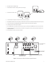
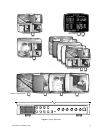
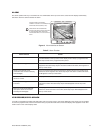
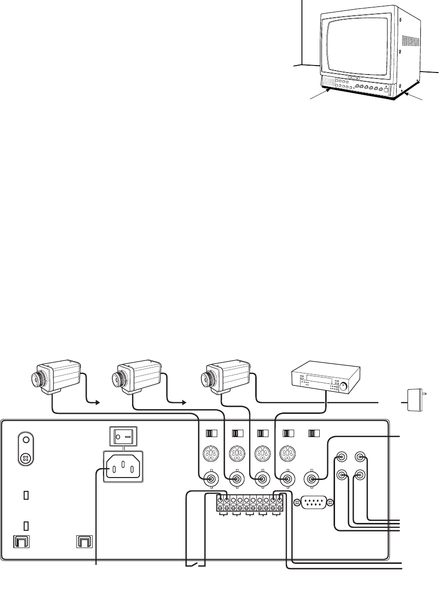
Figure 4. Connections at the Back of the Monitor (Optional Video)
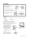
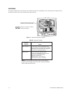
1. Place monitor on a stable surface such as a shelf or desk top.
2. Mount cameras or alternate video source using the appropriate
mounting device.
3. Run video cables of the proper length. The camera end of the
cable should have a connector that matches the camera con-
nector. The monitor end should use a BNC connector. Refer to
Installation Tips
.
4. Connect cables to cameras or alternate video sources.
5. If alarm contacts are used, run wires from the contacts to the
monitor and connect at the push-in connector on the back (refer
to Figure 4).
6. Connect video (BNC) cables to the desired channel IN/OUT
jacks on the back of the monitor (refer to Figure 4).
7. Set impedance switches to the 75-ohm position (refer to Figure 4).
8. Connect power to the camera or alternate video source. Use 24 VAC transformer or appropriate power supply.
9. If used, connect VCR to the VIDEO/AUDIO IN/OUT jacks on the back of the monitor (refer to Figure 4).
10. Connect AC power to monitor (refer to Figure 4).
11. Turn on MAIN switch on the back of the monitor (refer to Figure 4). Then press the POWER button on the front of the monitor.
12. The monitor begins operation using the factory set defaults. To re-program the monitor follow the procedure in Table A in the
Programming
section.
13. Test according to the check-out procedure in Table B.
BE SURE THERE IS AIR SPACE BELOW MONITOR.
DO NOT BLOCK AIR SPACE BY PLACING MONITOR ON A
SOFT SURFACE OR BY COUNTERSINKING SPOTS
FOR THE FEET.
MAIN
A/C INLET
CH 1
IN
IN/OUT
CH 3 CH 4CH 2
REMOTE
*
CH 1 CH 2 CH 3 CH 4 TRIG
OUT
IN
OUT
MONITOR
OUT
VIDEO AUDIO
75 Hi 75 Hi 75 Hi 75 Hi 75 Hi
SCREEN
FOCUS
TO AC
OUTLET
TO VCR (OPTIONAL)
IF AUDIO IS USED
TO VCR
TRIGGER
ALARM CONTACT
CAMERA OR ALTERNATE
VIDEO SOURCE 1
*
NOT USED IN STANDARD INSTALLATION. CONTACT
PELCO IF REMOTE CONTROL IS REQUIRED.
AC TRANS-
FORMER
CAMERA OR ALTERNATE
VIDEO SOURCE 2
CAMERA OR ALTERNATE
VIDEO SOURCE 3
CAMERA OR ALTERNATE
VIDEO SOURCE 4
24 VAC
TO VCR (WHEN
AUDIO IS NOT USED)
TO 24 VAC TO 24 VAC