


14 Pelco Manual C1968M-A (1/02)
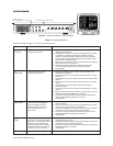
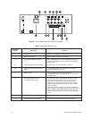
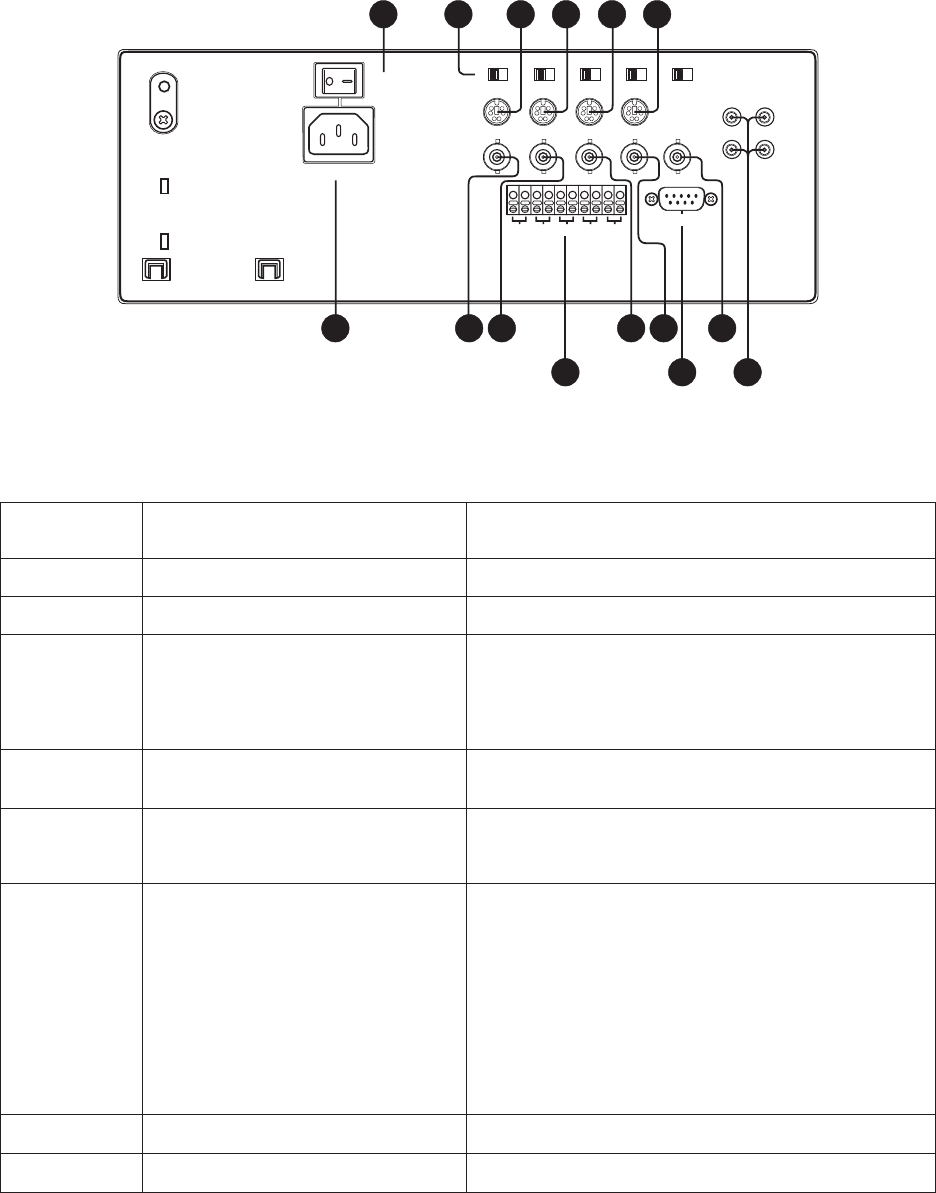
Table F. Back Panel Reference Key
Reference
Number Description Function
1Power inlet
2 Main power switch
3 75-ohm/High impedance switch
4-7 Video/Audio inputs (6-Pin Mini-DIN)
8-11 Video looping output/Camera input
(BNC)
12 Monitor output
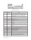
13 Alarm input/output connector
(10-position, snap-in type)
14 Remote control serial port (DB9)
15 VCR input/outputs (phono jacks)
Accepts 110 to 240 Volts AC, 50/60 Hz power.
Controls power to monitor and cameras.
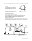
Set to 75-ohm position for normal installations. Set to HI
position when additional monitor is connected at the video
looping output.
Normal input to use with CCQ1400A-4 cameras.
Connect additional monitor to the channel or connect a
camera that uses BNC connector.
Connect additional monitor to the quad circuit.
The additional monitor will display the same information as
the main monitor.
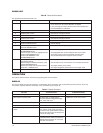
CH1, CH2, CH3, CH4: Connect alarm detection contacts
(works the same as the alarm inputs on the camera) or
alarm output to annunciators or other devices. Output
switches from 5 VDC to ground on alarm with N.O. alarm
contacts. Output switches from ground to 5 VDC on alarm
with N.C. contacts.
TRIG OUT: Connect a trigger input to start a VCR when an
alarm is detected. Trig Out switches from ground to 5 VDC on
alarm when Active Out (on the menu) is set for L. Trig Out
switches from 5 VDC to ground on alarm when Active Out is
set for H.
This is not used.
Interface video and audio signals to and from a VCR.
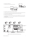
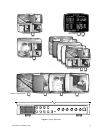
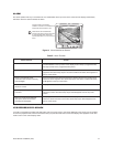
Figure 9. Monitor Back Panel Controls and Connections
MAIN
A/C INLET
CH 1
IN
IN/OUT
CH 3 CH 4CH 2
IN
OUT
MONITOR
OUT
VIDEO AUDIO
75 Hi 75 Hi 75 Hi 75 Hi 75 Hi
SCREEN
FOCUS
2 3
1
13
14
4
5
6
7
8
9
10
11
CH 1 CH 2 CH 3 CH 4 TRIG
OUT
12
REMOTE*
15