


Pelco Manual C1968M-A (1/02) 7
3. Run cables. Refer to
Installation Tips
.
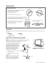
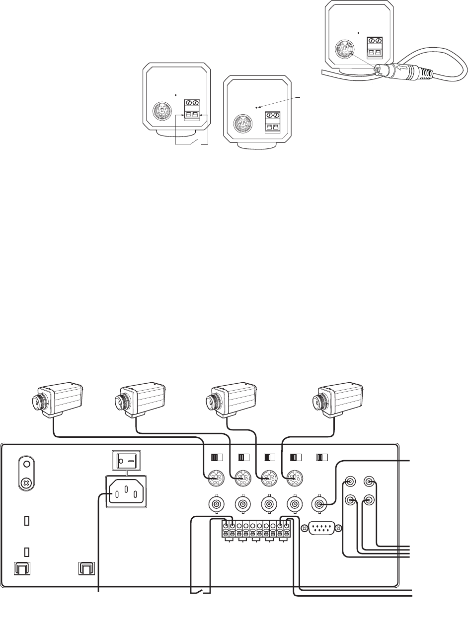
4. Connect cables to cameras. Insert plug with the arrow facing up.
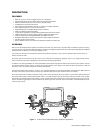
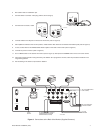
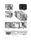
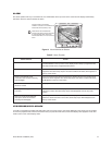
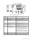
Figure 3. Connections at the Back of the Monitor (Supplied Cameras)
MAIN
A/C INLET
CH 1
IN
IN/OUT
CH 3 CH 4CH 2
REMOTE
*
CH 1 CH 2 CH 3 CH 4 TRIG
OUT
IN
OUT
MONITOR
OUT
VIDEO AUDIO
75 Hi 75 Hi 75 Hi 75 Hi 75 Hi
SCREEN
FOCUS
TO AC
OUTLET
TO VCR (OPTIONAL)
IF AUDIO IS USED
TO VCR
TRIGGER
ALTERNATE ALARM CONTACT
(WHEN CONTACTS ON THE
CAMERA ARE NOT USED)
CAMERA 1 CAMERA 2 CAMERA 3 CAMERA 4
*NOT USED IN STANDARD INSTALLATION. CONTACT
PELCO IF REMOTE CONTROL IS REQUIRED.
TO VCR (WHEN AUDIO
IS NOT USED)
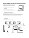
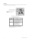
5. Connect alarm contacts, if used.
6. Connect cables to the IN jacks on the back of the monitor (refer to Figure 3).
8. Set impedance switches to the 75-ohm position, unless another video device is connected to the IN/OUT jacks (refer to Figure 3).
9. If used, connect VCR to the VIDEO/AUDIO IN/OUT jacks on the back of the monitor (refer to Figure 3).
10. Connect AC power to monitor (refer to Figure 3).
11 Turn on MAIN switch on the back of the monitor (refer to Figure 3). Then press the POWER button on the front of the monitor.
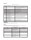
12. The monitor begins operation using the factory set defaults. To re-program the monitor, follow the procedure in Table A in the
Programming
section.
13.Test according to the check-out procedure in Table B.
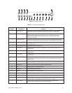
MIC
MONITOR
ALARM
IN GND
MIC
MONITOR
ALARM
IN GND
N.C. OR N.O. CONTAC
T
MIC
MONITOR
ALARM
IN GND
MICROPHON
E