


MODU-FIRE® FORCED DRAFT
Gas-Fired Boiler Maintenance
flow switch does not close, the red “low air”
light remains illuminated and the combustion
sequence does not go any farther.
5.5
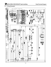
SEQUENCE OF OPERATION
1. When the 230V/1Ph/60Hz fused disconnect is
energized, there is power to the combustion
blower speed control. When the On/Off (boiler
power) switch is turned on, the power LED il-
luminates and power is provided to the flame
safeguard control and the transformer for the
temperature control. Power is also applied
through the “start logic string” which is a series
of normally closed switches, including water
flow, gas pressure, high stack temp, high limit
temperature, and operating temperature and fi-
nally into the flame safeguard programmer call
for heat.
7. Once sufficient air flow is indicated by the air
flow switch, and if the combustion chamber
back pressure is less than 4” w.c. indicating an
obstruction free vent, terminal 7 of the combus-
tion control is energized. This starts the 30 sec-
ond purge of the combustion chamber.
8. After the 30 second purge, a 4-second “trial for
ignition” period is initiated with Terminal, 8, 9
and 10 being energized. Terminal 10 of the
combustion control powers the ignition trans-
former and Terminals 8, and 9 energize the main
gas valve. The transformer output creates a
spark at the igniter.
2. The water flow limit switch is made when there
is water flow through the boiler and the red wa-
ter flow light is off.
9. After the 4 second “trial for ignition” period, if a
flame has been established, Terminal 10 of the
combustion control is de-energized. Terminal 9
remains energized. Terminal 21 is energized, re-
leasing the speed control to modulation. The
temperature control modulates the fan speed to
control the outlet water temperature and the gas
control valve modulates the gas input propor-
tional to the fan speed to maintain the desired
combustion characteristics.
Notice: The closing of this switch does not
prove that flow is adequate. It only indicates
that some flow is present. Refer to Section 3.8
for proper flow rates.
3. When adequate gas pressure is available, the low
gas pressure limit switch is closed. Manual reset
is required following conditions resulting in low
gas pressure.
10. When the load is below the low fire rating of the
boiler, the boiler will continue firing and the out-
let water temperature will rise until it reaches the
set point + 1/2 of the boiler differential setting.
At this point the operating control contacts open,
the combustion control is de-energized at Ter-
minal 6 and the indicator for HEAT is turned
off. This action also de-energizes Terminals 8,
9, and 21 thus closing the main gas control
valve. The speed control continues to run the
blower to post purge the combustion chamber.
4. When the temperature sensed by the high limit
temperature control is below the set limit, the
switch is closed. Manual reset is required fol-
lowing conditions exceeding high limit tempera-
ture.
5. When heat is required as indicated by the outlet
water temperature, power is applied to Terminal
6 of the programmer, which initiates the burner
ignition and operation sequence.
6. The programmer first energizes Terminal 4
which energizes relay 1. Normally open contacts
of relay 1 close enabling the run forward termi-
nal of the blower speed control. This drives the
blower to its start speed. The air flow switch
initially shows low air flow with the “LOW
AIR” indicator. This indicator will remain on
until sufficient air flow is sensed. If the fan
speed is insufficient for proper purge, the air
11. When the return water temperature is reduced by
the load on the system, the operating control
switch will close again. The operating sequence
will recycle to Step 5, provided the limits on wa-
ter flow, gas pressure and high temperature are
all met.
27