


MODU-FIRE® FORCED DRAFT
Gas-Fired Boiler Installation
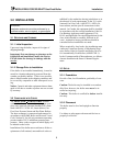
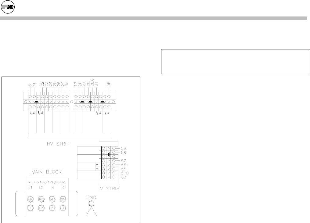
Notice: A dedicated earth ground (green wire) is
required to avoid nuisance shutdowns. Do not
ground through the conduit. It is also important that
proper polarity be maintained.
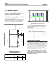
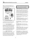
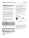
HEADER
SENSOR
OUTDOOR AIR
SENSOR
ANALOG INPUT
DIRECT DRIVE
4 - 20 mA
ANALOG
OUTPUT
0 - 10 V
START
INTERLOCK
120VAC
#1
OUTDOOR SETPOINT
OVERRIDE
120VAC
PUMP ENABLE
WITH DELAY OFF
DRY CONTACT
ALL LIMIT POINTS
ALARM
DRY CONTACT
FLAME FAILURE
ALARM 120VAC
PILOT DUTY ONLY
AUXILIARY
LOW WATER
CUTOFF
120VAC
START
INTERLOCK
120VAC
#2
BOILER RUN
INDICATOR
DRY CONTACT
SEE INSTALLATION & OWNER'S MANUAL FOR RATINGS AND DESCRIPTIONS
1912345678910 1112131415161718
12345678
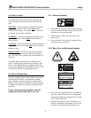
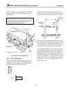
Boiler Electrical Connections
The junction box at the rear of the boiler contains
terminal strips for power and control connections.
These connections are described as follows:
Power Terminal Block
The boiler power circuit requires 208-240 volts, sin-
gle phase, 60 hertz, with a dedicated neutral for the
control circuit as labeled. The voltage from each
line (L1, L2) to the neutral must be approximately
115V AC. The 1500 & 2000 series boilers require
less than 12 amps. Before starting the boiler, check
to ensure that the proper voltage and amperage are
connected to the boiler and that the boiler is con-
nected to a suitable fused disconnect switch.
High Voltage (HV) Strip
#1 Start Interlock – Use for boiler enable. Closing
this circuit allows the boiler to run. Opening this
circuit prevents the boiler from running, provided
the remote/local enable switch is in the remote posi-
tion. This circuit is energized by the boiler. It has a
120VAC potential. Devices connected to these ter-
minals must be rated for 120VAC and 5 Amps.
WARNING: The remote/local switch bypasses the
#1 start interlock when in the local position. Do not
connect safety devices into #1 start interlock
Outdoor Air Override – Use for override of out-
door air schedule. Closing this circuit overrides the
outdoor air reset schedule to a fixed setpoint. Open-
ing this circuit allows the control to reset the set-
point based on outdoor air temperature when in out-
door air reset mode. This circuit is energized by the
boiler. It has a 120VAC potential. Devices con-
nected to these terminals must be rated for 120VAC.
Pump Enable w/Delay Off - This contact closes
when there is a call for heat. When the call for heat
is removed, the contact remains closed for a period
of time. Dry contact with a 120VAC 1 Amp max
rating. (See 3.12.1)
All Limit Points Alarm (ALPA) – Pilot duty alarm
contact that is closed if the boiler does not start
within five minutes of receiving a call for heat. Dry
contact with a 120VAC 1 Amp max rating.
Boiler Run Indicator – This contact closes when
the flame is on. Dry contact 120VAC 1 Amp max
rating.
Flame Failure Alarm – Alarm output from the
flame safeguard control. This circuit is energized
by the boiler. It has a 120VAC potential with a max
rating of 1 Amp.
Auxiliary Low Water Cutoff – These terminals are
used for connection of a low water cutoff. This cir-
cuit is energized by the boiler. It has a 120VAC
potential. Devices connected to these terminals
must be rated for 120VAC and 5 Amps.
#2 Start Interlock - Use for additional field safety
device to close this circuit. Closing this circuit al-
lows the boiler to run. Opening this circuit prevents
the boiler from running. This circuit is energized by
the boiler. It has a 120VAC potential. Devices
connected to these terminals must be rated for
120VAC and 5 Amps.
8