


MODU-FIRE® FORCED DRAFT
Gas-Fired Boiler Installation
wall or through the roof routing for the supply of
combustion air through a duct. It is important to
locate the intake duct in such a way that it does not
become blocked due to snow, ice, and other natural
or man-made obstructions.
3.5.2 Intake Duct Materials and Sizes:
Material: PVC, CPVC (Schedule 40), single wall
galvanized steel, or other suitable materials. The
intake duct must be sized for a maximum pressure
drop of 0.50 inches W.C. at 500 SCFM. The instal-
lation of a bird screen on the intake termination is
recommended.
3.5.3 Sealing the Intake Duct
Proper sealing of the intake ductwork is necessary to
prevent infiltration of air from conditioned spaces.
Joints in PVC or CPVC must be cemented. For gal-
vanized duct, wrap each joint and seam with adhe-
sive aluminum tape.
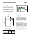
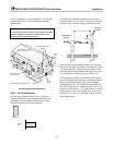
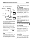
3.5.4 Intake Duct Connection to Boiler
Connect the air supply duct to the collar on the back
of the boiler. This collar is 7-7/8” OD. Fasten the
duct to the collar with sheet metal screws at 90º an-
gles. Wrap the joint with adhesive aluminum tape.
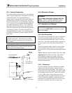
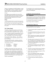
3.5.5 Intake/Exhaust Layout
A variety of configurations for the intake/exhaust
may be used.
Refer to Section 3.6.5 for required
clearances for all terminations. The inlet and/or
exhaust may be routed through the building sidewall
and/or the roof.
To prevent the possible re-
circulation of flue gases, the vent designer must take
into consideration such things as prevailing winds,
eddy zones, building configurations, etc. P-K can-
not be responsible for the effects such adverse con-
ditions may have on the operation of the boilers.
Dimensions specified in this document are mini-
mum clearances, and may or may not be sufficient
for conditions at a specific job site.
3.6
VENTING (STACK)
This boiler requires a special vent system.
This
boiler is not certified for use with Type "B" vent.
This boiler is a Category IV appliance as defined
in ANSI Z21.13/CSA 4.9, latest edition. The vent
material must be listed Category IV vent pipe (316L
or AL29-4C Stainless Steel) and comply with UL
1738 or UL 103. In Canada it must comply with
ULC-636. The exhaust vent can be run horizontally
or vertically.
Vent installations shall be in accordance with the
National Fuel Gas Code, ANSI Z223.1, Part 10 or
CSA B.149 code, or applicable provisions of the
local building codes.
The venting system and the horizontal portions of
the venting system shall be supported to prevent
sagging.
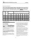
The vent must be sized according to the vent
manufacturer’s recommendations. Consult your
vent supplier for correct sizing and structural sup-
port requirements. Design calculations should be
based on a back pressure of 1.0 inches w.c. fric-
tional resistance in the vent with a stack temperature
of 325° F (gross) and a CO
2
level of 8.5% (natural
gas) or 9.9% (propane). These values are to be used
for vent sizing calculations. The maximum certified
back pressure allowable is 2.0 inches w.c. frictional
resistance.
The boiler has an 8” OD connection for the vent.
This connection may be reduced to 6” diameter pro-
vided the above backpressure conditions are met. A
reducer is available from the factory for this pur-
pose. Additional care must be used with sidewall
venting as the exhaust velocity is high and the ex-
haust gas plume may extend significantly beyond
the termination.
In addition to the information provided in this man-
ual, visit the Gas Appliance Manufacturers Associa-
tion’s (GAMA) web site (www.gamanet.org) for a
series of flash videos explaining the proper selection
and installation of venting systems for gas appli-
ances.
10