


MODU-FIRE® FORCED DRAFT
Gas-Fired Boiler Installation
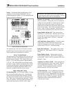
Low Voltage (LV) Strip
Header Sensor – Connected when a header sensor
is used. The temperature control should be in Mode
2 or 5. The sensor is available from the local P-K
Representative.
Outdoor Air Sensor – Location for outdoor air sen-
sor wires to be connected. The temperature control
should be in Mode 4 or 5. The sensor is available
from the local P-K Representative.
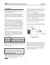
Analog Input Direct Drive – Remote signal for
controlling the boiler firing rate directly. Input 4-20
mA signal only. The temperature control should be
in Mode 6. (See 3.12.1)
Analog Output – Boiler output 0-10VDC, indicat-
ing approx firing rate/modulation percentage of the
burner.
3.5
COMBUSTION AIR
Combustion air must be free from dust, lint, etc.
The presence of such materials in the air supplied to
the burner could cause nuisance "Low Air" shut-
downs or premature burner failure. The boiler
should not be operated during construction while the
possibility of drywall dust, demolition dust, etc. ex-
ists.
Provisions for combustion and ventilation air must
be in accordance with the National Fuel Gas Code,
ANSI Z223.1, Section 8.3, latest edition, or applica-
ble provisions of the local building codes. The for-
mula is "1 sq. in. per 1,000 Btu/hr of gas input not
less than 100 sq. in." The location shall be "neither
more than 18 inches, nor less than 6 inches above
the floor level."
In Canada, combustion air openings shall comply
with CSA B149.
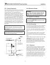
The boiler room shall be provided with two open-
ings to ensure adequate combustion air and proper
ventilation. One opening should be 6 to 12 inches
above the floor and the other 6 to 12 inches below
the ceiling, preferably on opposite walls. The size
of each opening is determined by whether air is
taken from inside or outside the building. In Can-
ada, ventilation air openings shall be at least 10% of
the cross sectional area required for combustion air,
but not less than 10 square inches. It is to be located
at the highest practical point communicating with
outdoors.
If air is taken directly from outside the building,
each opening should have a net free area of 1 square
inch for each 4,000 Btu per hour of total boiler in-
put. For instance, 300 square inches (2-1/12 square
feet) are required for 1,200,000 Btu per hour input.
When air is taken from the outdoors through a verti-
cal duct, 1 square inch per 4,000 Btu per hour is re-
quired. If a horizontal duct is used, 1 square inch
per 2,000 Btu per hour is required, i.e., 600 square
inches for 1,200,000 Btu per hour input.
If air is taken from another interior space, each
opening should have a net free area of 1 square inch
for each 1,000 Btu per hour of boiler input (i.e.
1,200 square inches for a 1,200,000 Btu/Hr boiler.)
WARNING!
Under no circumstances shall the boiler room ever
be under a negative pressure. Particular care
should be taken when exhaust fans, compressors,
air-handling units or other equipment may rob air
from the boiler.
The combustion air supply must be completely free
of chemical fumes which may be corrosive when
burned in the boiler. Common chemicals which
must be avoided are fluorocarbons and other halo-
genated compounds, most commonly present as re-
frigerants or solvents, such as freon, trichlorethyl-
ene, perchlorethylene, chlorine, etc. These chemi-
cals, when burned, form acids which quickly attack
the boiler tubes, tube sheets, flue collectors and the
boiler vent. The result is improper combustion and
premature boiler failure.
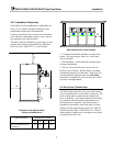
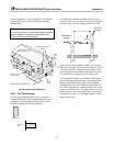
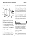
3.5.1 Sealed Combustion
The boilers are also certified for operation with a
sealed combustion air system. Such a system em-
ploys a sealed combustion air intake duct leading
from outdoors to the boilers. Air flow through the
system is maintained by the fan inside the boiler
assembly. Typical installations utilize through the
9