


14
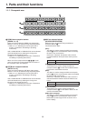
Installation and connections
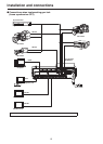
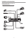
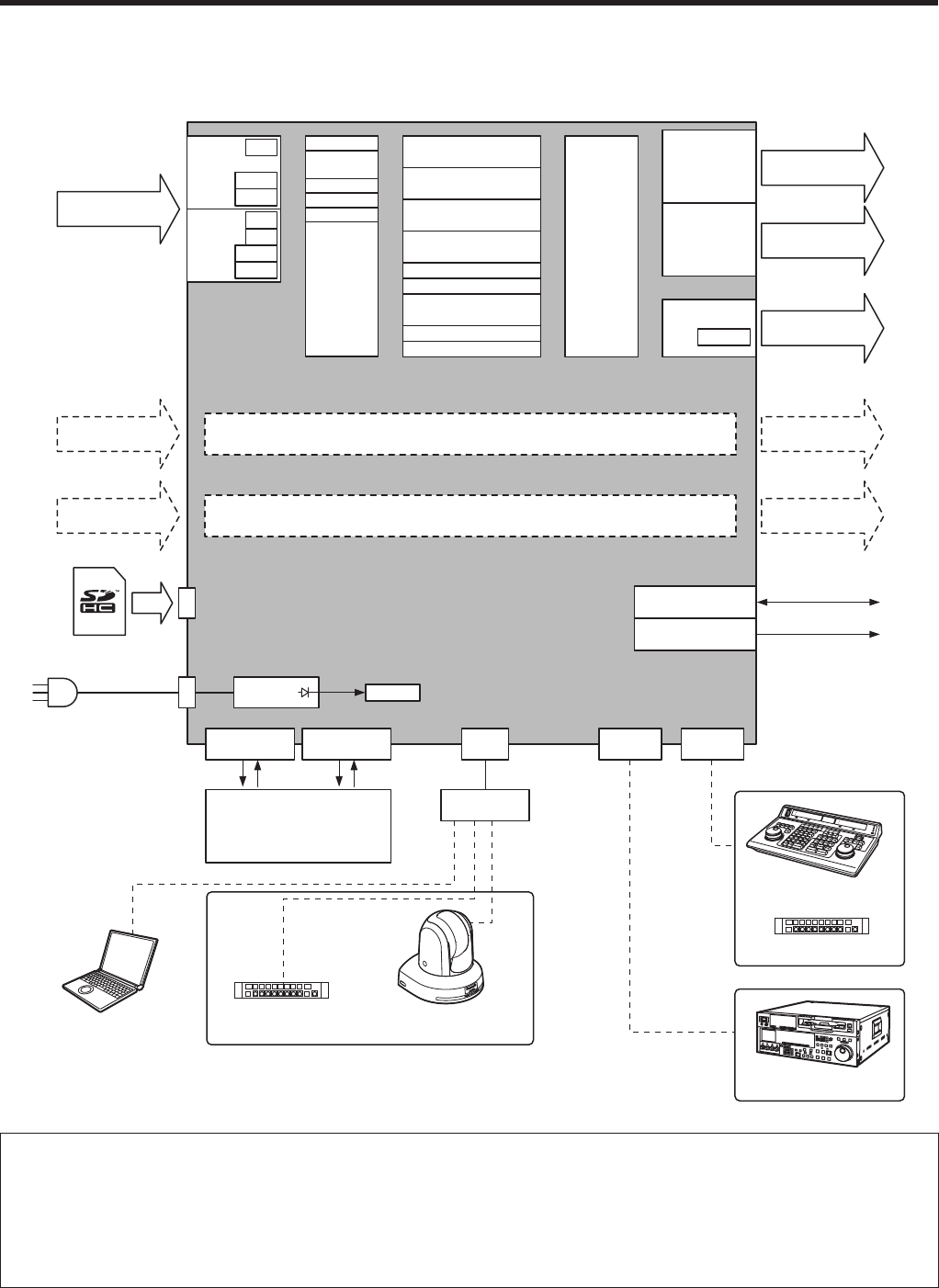
pw Connections with other devices
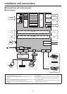
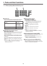
pqBlock diagram
SDI Input
1 to 8
Memory card
Input
A1, A2
Input
B1, B2
Output
A1, A2
Output
B1, B2
Black
STILL1, 2
CLIP1, 2
Input
matrix
ColorBar
Color
BKGD1, 2
SDI OUTPUT
1-1, 1-2
Output
matrix
SDI Output
1-1, 1-2 (
3)
SDI OUTPUT
2 to 5
SDI Output
2 to 5
DVI-D Output
~ AC IN
PowerAC/DC
SDI IN
5 to 8
FS
UC
VPrc
DbyD
DVI-D OUT
Scaler
SDI IN
1 to 4
FS
VPrc
DbyD
BKGD
CUT, MIX, WIPE, DVE
KEY
CUT, MIX, WIPE, DVE
AUX 1 to 4
WFM
MEM PVW
FTB
Multi View
DSK
CUT, MIX
PinP1, 2
CUT, MIX
Option slot A
Option slot B
REF IN/OUT (
1)
REF OUT (
2)
Reference signal
TALLY/GPI 1
Dsub 15
GPI-IN: 8
GPI-OUT: 19
ALARM OUT: 1
GND: 2
TALLY/GPI 2
Dsub 15
Editing controller
Aux panel
VTR, etc.
Switching
hub
COM
Dsub 9
EDITOR
Dsub 9
LAN
RJ45
Remote cameraAux panelComputer
(
4)
(
5)
1: When external synchronization is selected as the reference signal
setting, the reference signal is input.
When internal synchronization is selected, the reference signal is
output.
2: When external synchronization is selected as the reference signal
setting, the signals are looped through and output.
When internal synchronization is selected, the reference signal is
output.
3: Two sets of the same output signals are distributed from
SDI OUTPUT 1.
4: Use a crossover cable when connecting the unit and another
device on a 1:1 basis without going through a switching hub.
5: Use a switching hub.
Proceed with the connections after reading the section entitled
“Network security” (on page 6).