


27
1. Parts and their functions
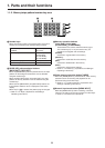
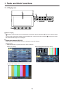
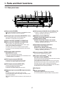
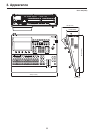
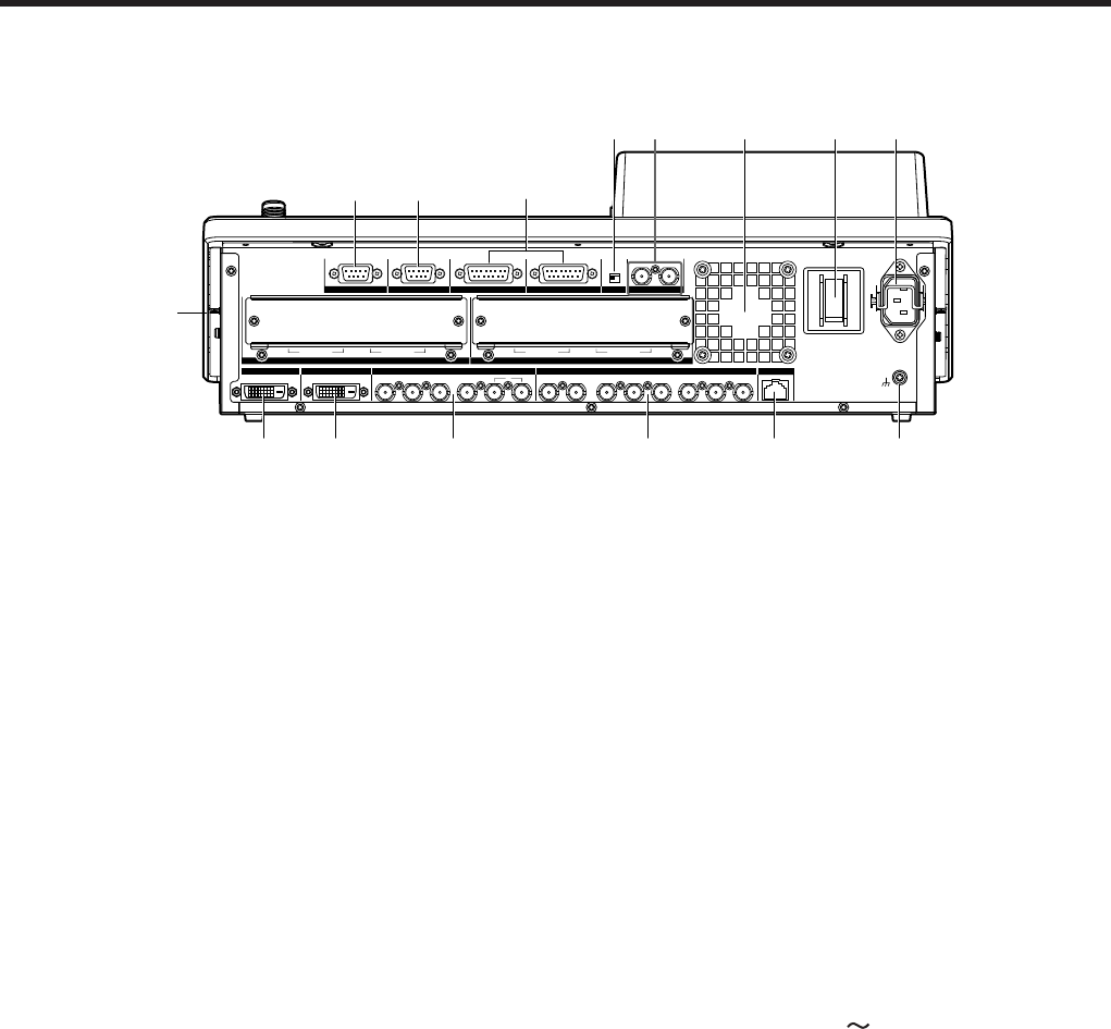
1-2. Rear panel area
ON
OFF
POWER
~AC IN
GND
SIGNAL
LAN
SLOT A
IN/OUT A1IN/OUT A2IN/OUT B1IN/OUT B2
SLOT B
DVI
-
D INDVI
-
D OUT
SV NM
4 3
SDI OUTPUTS
125 8 7 6 5 4 3 2 1
SDI INPUTS
EDITOR COM TALLY/GPI 2 TALLY/GPI 1 REFBOOT
Power switch [POWER]
When the power switch is turned on, the POWER indicator
(1) lights up, and the unit can be operated.
SDI signal input connectors [SDI INPUTS 1 to 8]
The up‑converter function can be used for the
SDI INPUT 5 to SDI INPUT 8 connectors.
Option slot SLOT A [IN/OUT A1, IN/OUT A2]
Option slot SLOT B [IN/OUT B1, IN/OUT B2]
Each of these is an input/output option slot.
A DVI input board, analog output board or other option
board can be installed in these slots.
For details, refer to “How to install the option boards”
(on page 12) and the operating instructions of the board
concerned.
SDI signal output connectors
[SDI OUTPUTS 1 to 5]
These can be allocated by the menus.
Two sets of the same output signals are distributed from
the SDI OUTPUT 1 connector.
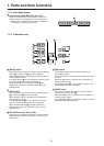
DVI-D input connector [DVI-D IN]
Connect to the computer with the DVI‑D cable.
The DVI‑I connector cable cannot be used.
DVI-D output connector [DVI-D OUT]
Connect a monitor that supports DVI‑D.
It can be allocated by the menus.
The DVI‑I connector cable cannot be used.
Reference input connector/BB output connector
[REF]
Loop‑through output in the external sync mode.
If the loop‑through output is not going to be used, provide
a 75‑ohm termination.
BB signals output from both connectors in the internal sync
mode.
LAN connector [LAN] (RJ-45) (10/100 Base-TX)
Refer to “4. External interfaces” (<Operations and
Settings> Operating Instructions).
EDITOR connector [EDITOR]
(RS-422, D-sub 9-pin, female, inch screw)
COM connector [COM]
(RS-422, D-sub 9-pin, female, inch screw)
Refer to “4. External interfaces” (<Operations and
Settings> Operating Instructions).
TALLY/GPI input/output connectors
[TALLY/GPI 1, TALLY/GPI 2]
(D-sub 15-pin, female, inch screw)
Refer to “4. External interfaces” (<Operations and
Settings> Operating Instructions).
Ground connector [SIGNAL GND]
Connect to the system’s earth ground.
AC power input socket [
AC IN]
(AC 100 V to 240 V, 50/60 Hz)
Connect one end of the supplied power cable to this socket
and the other end to the AC outlet.
The supplied power cable comes with a 3‑pin power plug.
Be absolutely sure to plug it into a 3‑point power outlet as
the power source in order to earth the unit securely.
If a 3‑point power outlet is not available for this connection,
be absolutely sure to consult your dealer.
Cooling fan
BOOT switch [BOOT]
This switch is used for maintenance purposes.
For normal operations, select the “NM” (normal) position.