


17
1. Parts and their functions
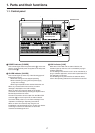
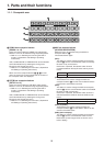
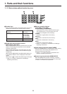
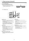
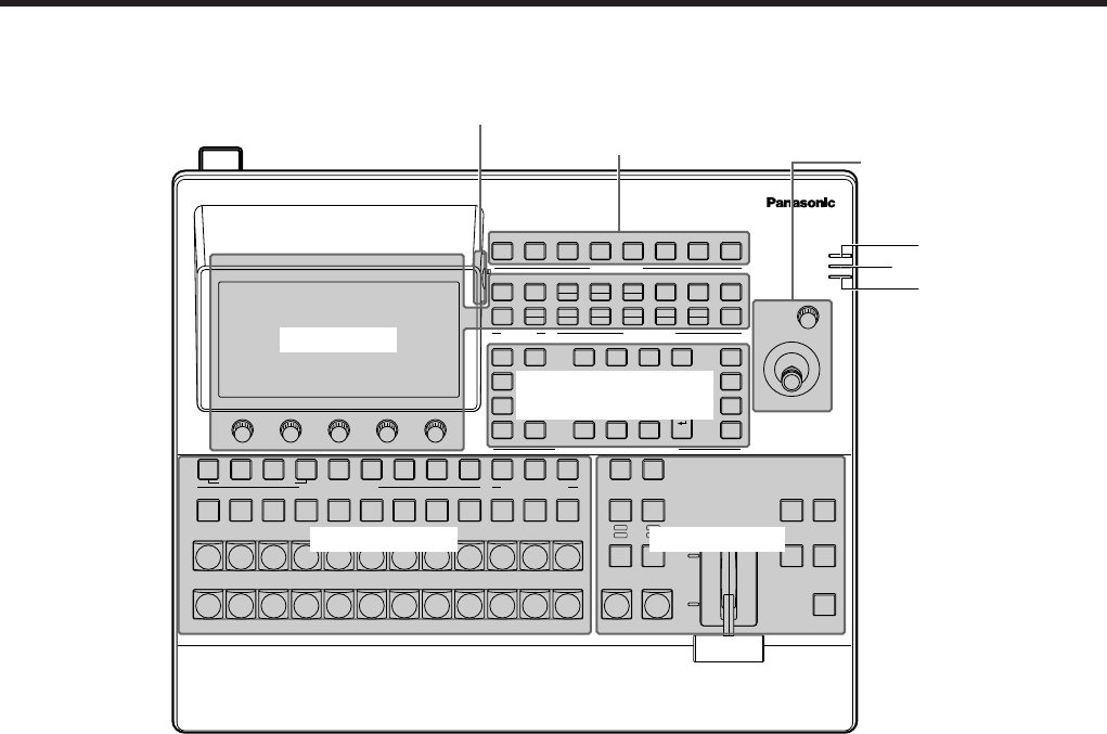
1-1. Control panel
4
INS
POWER
ALARM
LINK
Live Switcher AV-HS410
U1 U2 U3 U4 U5 U6 U7 U8
USER BUTTON
MENU
MODE
PICT
DSK
TIME
PLUGIN
BKGD
CBGD
KEY
CHRKEY
PinP1
PinP2
MENU
HOLD
XPT
MV
IN
OUT
CONFIG
SYS
MENU
OFF
WFM
VECT
VMEM
SD Card
SHOT
EVENT
DISPLAY MENU SELECT
POSITIONER
X/Y
Z
MENU
INPUT
VMEM
BKGD
PATT
KEY
PATT
TAKE
ENTER
�/
+
PAGE
PLAY
REC
STOP
XPT
DSBL
<
CLIP 1
STILL 1
MEMORY / WIPE PATTERN / 10 KEY
<<
TRIM OFF
>>
CLIP 2
STILL 2
REV
TRIM OUT
TRIM IN
9
PASTE
6
MOD
3
REV
C
UNDO
8
COPY
5
DEL
2
>
.
>>
7
NEW
1
<
0/10
<<
STORE
RE
CALL
EDIT
DEL
SHOT
MEM
EVENT
MEM
PLUGIN
MEM1
PLUGIN
MEM2
>
F1 F2 F3 F4 F5
AMBER : FILL / GREEN : SOURCE
KEY PinP1 PinP2 DSK AUX1 AUX2 AUX3 AUX4 DISP MV
AUX BUS DELEGATION
PGM
A
PST
B
AUX
1/13
2/14
3/15 4/16 5/17 6/18 7/19 8/20 9/21 10/22
11/23
12/24
AUX/DISP SOURCE
SHIFT
SHIFT
SHIFT
PGMPVW
CUT
AUTO
MIX
MIX
WIPE
N/R
R
BKGD
KEY
KEY
ON
FTB
ON
PinP1
ON
PinP2
ON
DSK
ON
WIPE DIRECTION
WIPE
MIX
WIPE
Display area
User button area
Positioner area
Transition areaCrosspoint area
Memory/wipe pattern/
number key area
Memory card area
1
POWER indicator [POWER]
This indicator lights when the power switch () on the rear
panel is set to ON while power is supplied to the AC power
input socket ().
2
ALARM indicator [ALARM]
This indicator lights up when any of the following types of
trouble has occurred.
• When the cooling fan has stopped operating
• When something is wrong with the power supply
(a drop in the voltage)
• When high temperatures are reached inside the unit
When any of these events has occurred, an alarm
message is displayed on the built‑in display.
When an alarm has occurred, details of the trouble
concerned can be checked by selecting the System menu
followed by the Alarm sub menu.
The alarm information can be output from the TALLY/GPI
connector () on the rear panel to an external device.
For further details, refer to “3‑7‑2. Alarm message” in the
<Operation and Settings> Operating Instructions.
When an alarm has occurred, stop using the unit
immediately, and be absolutely sure to contact your dealer.
Continuing to use the unit even after an alarm has
occurred could damage the unit.
3
LINK indicator [LINK]
While the unit is linked with an external device, this
indicator lights up when the unit is controlled by a plug‑in
software application.
For the settings used when the unit is to be controlled by a
plug‑in software application, check out the specifications of
the application concerned.
For the settings to be performed for the external device,
refer to the operating instructions of the device concerned.