Series 8900SH Control Panel Operation And Installation Manual
Section 1 Introduction And Specifications
SECTION 1: INTRODUCTION
This manual explains the operation, installation and control of TRIAD Boilers using the
Series 8900 Microprocessor Control Panel. This manual provides information needed to
operate the panel and to fine-tune the boiler system depending on the requirements of the
structure that requires heating.
We have taken care to make this manual as easy to understand as possible, and to
anticipate common questions that might be asked. If we missed something along the way,
please feel free to call us or your TRIAD Manufacturer’s Representative with ideas and
suggestions.
INSTALLATION PROCEDURES:
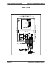
The Series 8900SH Control Panel requires 120V A.C., 5 AMP, 60 Hz single phase to
operate. Service wiring should be run in an approved manner using black and white wire.
Minimum wire size shold be 14 guage or as local code requires.
After running the service wire to the panel, connect to the fuse block and neutral terminal,
which is marked. Be carefull that the panel is not mounted in an area that could experience
temperatures above 125°F.
Mounting the Outside Sensor:
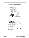
The outdoor sensor is to be mounet on the North or Northwest outside wall of the building.
The sensor should be mounted no less than twelve feet above the ground. In a high-rise
installation, when the equipment room is on the top floor, install the sensor as close as
possible to the panel with it still on a North wall. Caution – Do not mount the sensor near a
heat source such as an air handler or lighting fixture.
Mounting the Return Line Sensor:
The immersion sensor is to be installed in the return side on the Primary Main of the boiler
system, at least 12 inches away from the nearest boiler.
Use 18 gauge solid copper wire between the senors and the control panel.
Use 18 gauge or heavier coded thermostat wire to connect the low voltage terminals
between the boiler and the control panel.
TRIAD recommends that the boilers be numbered. The terminal strip in the panel is
prenumbered at the factory. Direction of flow through the Primary Main should be noted.
The #1 boiler is at the “Supply End” of the Primary Main. The last boiler in the series is on
the “Return Side”.
Connect each boiler to the control panel ensuring that each boiler number is connected to
the corresponding number in the control panel. Maintain polarity! This means all first


