


Series 8900SH Control Panel Operation And Installation Manual
Section 7 Error Codes
SECTION 7: ERROR CODES
Error codes are the way the control panel indicates if there are any system problems or faults.
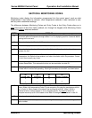
DISPLAY EXPLANATION
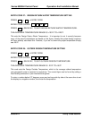
230
If this is displayed after entering any of codes 11, 12, 73, 74, 75, or 76, then you have
an Open Sensor, which means the sensor is bad, or the wire connected to the sensor
input terminal is broken. See Section No. 5, Sensor Troubelshooting to test.
-40
If this is displayed after entering any of codes 11, 12, 73, 74, 75, or 76 then you have
either a bad sensor, or the polarity at the sensor input terminals is reversed. See Section
No. 5. Sensor Troubelshooting to test.
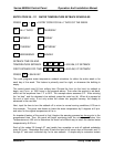
CODE N.A.
This will display if you attempt to enter a code the panel does not recognize. Make sure
you are using a valid code.
OUT OF
RANGE
Some codes have limits. For example, code 26 tells the panel the number of boilers in
the system. The maximum number it can operate is 24, so if 25 was entered the display
would read “out of range”.
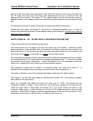
PROG
LOSE
This display, which means program lost, could be an indication of any of the following:
1. The first time the control panel is powered up PROG LOSE may flash. Press * (star)
to reset the computer and then proceed with entering the codes.
2. If pressing * (star) does not clear the display, the E- PROM chip may be bad. Contact
your TRIAD service representative or TRIAD Boiler Systems for a replacement.
3. If the replacement of the E-PROM chip does not solve the problem. the batteries may
have gone bad. In this case the computer will have to be returned to the factory for
service.
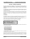
Replacement of E-PROM Chip:
The E-PROM Chip can be replaced if (i) it fails or (ii) to update the program and keep it tailored
to the heating system.
THE E-PROM CHIP HAS A NOTCH ON ONE END. WHEN THE CHIP IS INSERTED INTO
THE SOCKET IT IS CRITICAL THAT THIS NOTCH LINES UP WITH A MATCHING NOTCH
ON THE RIGHT SIDE OF THE SOCKET. INSERTING THE CHIP WITH THE NOTCH TO THE
LEFT WILL PERMANENTLY DISABLE THE E-PROM.
To insert the chip in the socket, gently rest the upper pins in the upper sockets without
applying any downward pressure, and then insert the lower pins into the lower sockets. DO
NOT FULLY INSERT THE PINS! With all pins properly alligned, place your fingers behind the
circuit board to prevent it from bending, and your thumbs on the top of the EPROM. Apply slow
and even downward pressure with your thumbs until the pins are snugly seated.