


L NAPCO Security Systems
Freedom F-64 Installation Instructions
WI1501A 9/06
Page 5
SPECIFICATIONS
Freedom F-64 Control Panel
O
perating Temperature: 0-49°C (32-120°F)
Input Power: 16.5-18.0 VAC via CLASS 2 Plug-In 20VA, 40VA or 50VA Transformer
Loop Voltage: 10-13Vdc
Loop Current: 3mA without Zone Doubling, 2.4mA with Zone Doubling using a 2.2K Ohm end-of-line resistor (Model EOL2.2K);
5mA for 2-wire smoke-detector zones; 1.4 mA using a 3.9K Ohm resistor (Model EOL3.9K) with Zone Doubling; 3mA with Se-
ries Zone with Loop Supervision and 3mA with Series Zone Doubling with Loop Supervision
Loop Resistance: 300 Ohm max.; 50 Ohm for 2-wire smoke-detector zones
Alarm Voltage Output: 1
Programmable Negative Outputs: 2
Auxiliary Power Output: 11.7-12.5 VDC
Remote Power Output: 12 VDC regulated (for the F-64PROG programmer)
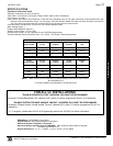
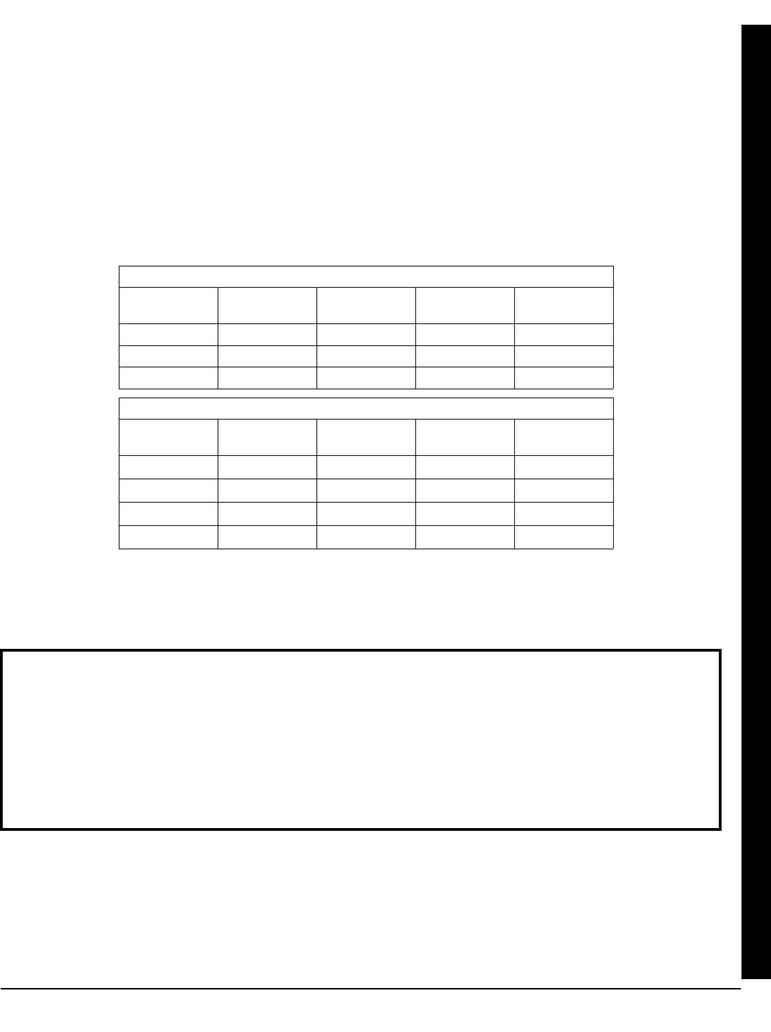
Combined Standby Current (Remote Power + Aux. Power + Fire Power): See following charts.
NOTE:
(1)
Alarm current can be increased by reducing standby current by the same amount.
* Not evaluated by UL.
** Commercial Burglary specifications not evaluated by UL.
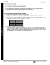
16.5VAC
TRANSFORMER
BATTERY
(12 VDC)
STANDBY
CURRENT
ALARM
CURRENT
STANDBY
TIME
40VA/50VA 7 AH 550 mA 450 mA
(1)
4 Hours
20VA* 7 AH 500 mA 2.0 A 4 Hours
20VA* 7 AH 500 mA 2.0 A 6 Hours
RESIDENTIAL BURGLARY & COMMERCIAL BURGLARY**
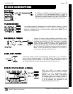
16.5VAC
TRANSFORMER
BATTERY
(12 VDC)
STANDBY
CURRENT
ALARM
CURRENT
STANDBY
TIME
40VA/50VA 7 AH 120 mA
520 mA
(1)
24 Hours
40VA/50VA * Two 7 AH 360 mA
280 mA
(1)
24 Hours
20VA * 7 AH 120 mA
360 mA
(1)
24 Hours
20VA * Two 7 AH 360 mA
120 mA
(1)
24 Hours
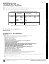
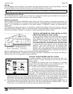
COMBINATION RESIDENTIAL FIRE & RESIDENTIAL BURGLARY
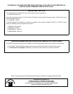
FOR ALL UL INSTALLATIONS
"ENABLE RESIDENTIAL FIRE" (ADDRESS 1422) MUST BE PROGRAMMED
The feature "Enable Residential Fire" (address 1422, option 4) must be programmed for ALL UL installations.
"DISABLE SYSTEM TROUBLE AUDIBLE TIMEOUT" (ADDRESS 2051) MUST BE PROGRAMMED
The feature "Disable System Trouble Audible Timeout" (address 2051, option 7) must be programmed for ALL UL
installations.
To program, please refer to the F-64 Programming Instructions (WI1502) for further information.
EZM Module: GEM-EZM4/8: Input, 50mA
Keypad Current: See keypad Installation Instructions.
Maximum Number of Keypads / Touchpads: 7
Maximum Wiring Length for each run (#22AWG): 1000' divided by total number of keypads /
Touchpads and EZMs on run
Keypad Dimensions: 4” x 5” x 1” (HWD); 11.1cm x 14.9cm x 2.7cm (HWD)
Specifications