Freedom F-64 Installation Instructions
L NAPCO Security Systems
WI1501A 9/06
Page 36
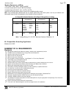
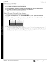
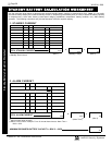
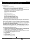
STANDBY-BATTERY CALCULATION WORKSHEET
Use the procedure given below to determine the required standby battery capacity in Ampere-Hours (AH). Note: It is not totally
accurate to merely multiply the combined standby current (in amperes) by the standby time (in hours) to obtain the battery capacity
(in ampere-hours), since other factors (control-panel charging capabilities, temperature, battery condition, etc.) affect battery
operation. The following calculations will yield the theoretical minimum required capacity.
1. STANDBY CURRENT
STANDBY CURRENT (Amps)
DEVICE QTY EACH TOTAL
F-64 Control Panel 1 X 0.120 = 0.120
GEM-EZM4/8 X 0.050 =
GEM-EZM8 X 0.050 =
RM3008
X 0.040 =
X
X
X
=
TOTAL STANDBY CURRENT
Amps
(1)
Alarm current drawn in alarm.
(2)
Alarm Time in Hours. Example: For a 15 minute alarm timeout, Alarm Time =
15/60 = 0.25.
2. ALARM CURRENT
ALARM CURRENT (Amps)
DEVICE QTY EACH TOTAL
TOTAL STANDBY CURRENT (from Box 1, above)
F-64 Panel
(1)
1 X 0.100 = 0.100
BELLS X =
STROBES
X =
HORNS / STROBES X =
X =
X =
Amps
TOTAL ALARM CURRENT
(1)
Standby Time in Hours.
(Box 1)
X
Hours
=
AH.
(Standby Time)
(1)
(Box 2)
X
Hours
=
AH.
(Alarm Time)
(2)
(Box 3)
MINIMUM REQUIRED BATTERY CAPACITY = BOX 2 + BOX
AH.
Standby-Battery Calculation Worksheet