


display of the panel, the yellow light-emitting diode 'Technical message' and the buzzer are activated
by these messages also.
Technical messages of that kind are:
The processing of a sabotage-message of a key safe.
Usually this message is reported to a burglar alarm control panel and indicated there as a burglar
alarm- or sabotage message. If no burglar alarm system is installed in the building the sabotage mes-
sage can be reported to the fire detection control panel and can be shown on the LC-display as tech-
nical message.
The activation of an extinguishing system.
The confirmation of the executed activation of the primary transmitting device.
5.5 Fault-message condition
The cause of the fault-message condition can be either the activation of a detector zone for faults (e.g.,
the surveillance of weight- or pressure loss of the extinguishing agent in extinguishing systems) or a
fault of a function of the fire detection system itself. Faults of the fire detection system can concern the
connection lines (e.g., broken wire, short-circuit, earthing) between individual parts of the system, the
power supply, single detectors, the control panel itself, etc.
Every current fault affects the function of the whole fire detection system. Be aware that a part of a
system that has a fault is out of function in its whole. For example, a faulty fire detector zone cannot
detect a fire in this detector zone! Have the fault repaired immediately by a company authorized and
trained by the manufacturer. Pay attention to the statements starting page 9 in Chapter 1.2.2: "What to
do in case of a fault"!
Not all parts of a fire detection system can be checked on continuously. A fault of a part of the system
that is not automatically surveilled constantly can be detected only during maintenance or during the
periodic testing of its functions by the user.
The fault-message condition is displayed on the control panel as follows:
The yellow summary display 'FAULT' is flashing.
The internal buzzer is sounding constantly.
You can reset the internal buzzer by using the button 'Silence buzzer'. The buzzer is activated again
by each new fault and can be reset in the same way.
The menu jumps automatically to the menu point [Faults] if no event of higher priority is currently
on the control panel.
The first line of the LC-display shows the first occurred fault. The second and third line display, de-
pending on the kind of fault, additional text (e.g., a zone-, respectively an element-specific text) for
the fault displayed in the first line. The fourth line is reserved for displaying fire alarms. The faults
are numbered in the order of their occurrence.
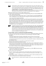
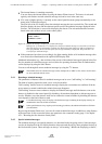
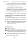
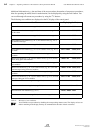
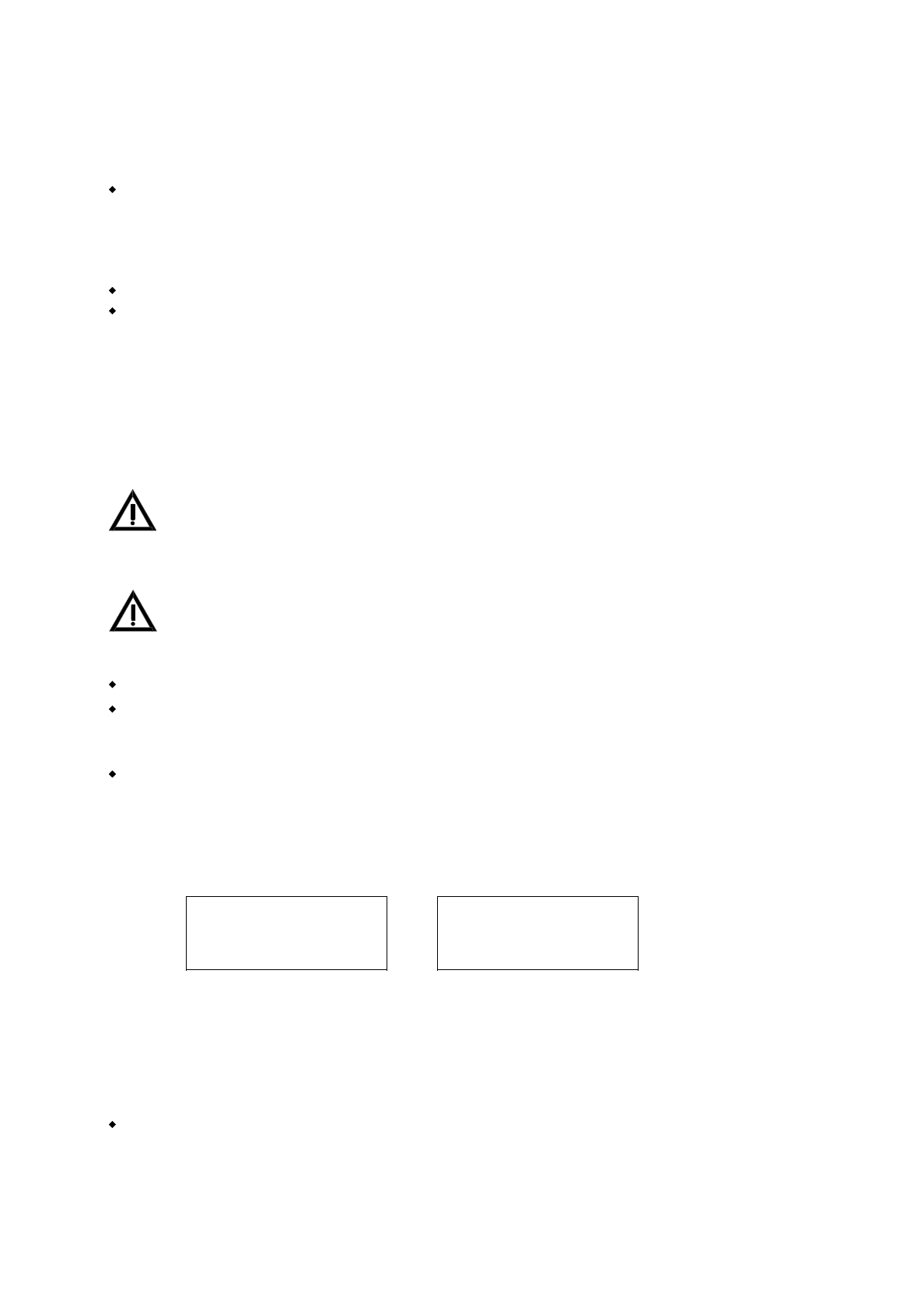
1.FAULT 0011/029
<zone text1>
<element text>
1.FLT-ALARM 0012/028
<zone text1>
<element text>
Figure 20: Examples of displays in fault condition
Left figure: Element Nr. 29 in detector zone Nr. 11 is displayed as the first received fault message.
Right figure: The activation of fault detector Nr. 28 in detector zone Nr. 12 is displayed as the last
fault alarm.
The second and third line show text information on the displayed fault. Has no element text been pro-
grammed, the second line of the zone text (if available) is displayed. The fourth line is reserved for
fire alarm messages.
Have the parameters been set to transmit the current fault to a transmitting device for fault mes-
sages, the red light-emitting diode 'Actuation activated' is illuminated to indicate that the transmit-
ting device has been activated.
HB216AE.SAM / 0130 / AN9161202
ZN5002/73/58
58
Chapter 5 • Operating conditions of fire detection control panels Series BC216 User Manual Series BC216 / Part A