


27
ƽ WARNING
When re-tightening the set screw, be sure
to tighten securely to prevent gas leaks.
Do not check for gas leaks with an open
fl ame -- use the bubble test. Failure to
use the bubble test or check for gas leaks
can cause severe personal injury, death, or
substantial property damage.
14. Turn on the gas supply at the manual gas valve.
15. Turn the power switch to the “ON” position.
16. Adjust the temperature set point on the control panel of
the SMART SYSTEM control module to the desired
water temperature so the appliance will call for heat.
17. Check burner performance by cycling the system while
you observe burner response. The burner should ignite
promptly. Flame pattern should be stable. Turn system
off and allow burner to cool, then cycle burner again to
ensure proper ignition and fl ame characteristics.
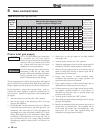
Gas pressure
The gas pressure must remain between 4 inches w.c. (.99
kPa) minimum and 14 inches w.c. (3.5 kPa) maximum for
Natural gas and between 8 inches w.c. (1.9 kPa) minimum
and 14 inches w.c. (3.2 kPa) maximum for LP gas during
standby (static) mode and while in operating (dynamic)
mode. If an in-line regulator is used, it must be a minimum
of 10 feet (3 m) from the Outdoor Knight XL boiler. It is
very important that the gas line is properly purged by the gas
supplier or utility company. Failure to properly purge the
lines or improper line sizing, will result in ignition failure.
The problem is especially noticeable in NEW LP installations
and also in empty tank situations. This can also occur when
a utility company shuts off service to an area to provide
maintenance to their lines.
Gas valve replacement
The gas valve MUST NOT be replaced with a conventional
gas valve under any circumstances. As an additional safety
feature, this gas valve has a fl anged connection to the venturi
and blower.
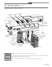
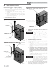
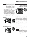
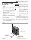
Figure 4-5 Inlet Gas Supply Check - Model 400
DETAIL
IMG00414
LOOSEN THE SET SCREW ONE (1) FULL TURN
A
ND PLACE THE MANOMETER TUBING OVER
THE PRESSURE TAP
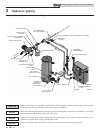
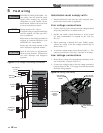
Figure 4-6 Inlet Gas Supply Check - Model 501
DETAIL
IMG00415
LOOSEN THE SET SCREW ONE (1) FULL TURN
A
ND PLACE THE MANOMETER TUBING OVER
THE PRESSURE TAP
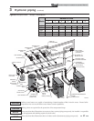
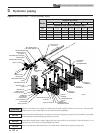
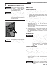
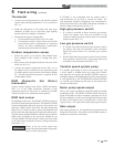
Figure 4-7 Inlet Gas Supply Check - Models 601 - 801
DO NOT adjust gas valve outlet pressure.
Attempting to alter the gas valve outlet
pressure could result in damage to the
valve, causing potential severe personal
injury, death, or substantial property
damage.
Failure to follow all precautions could
result in fi re, explosion, or death!
ƽ WARNING
ƽ WARNING
DETAIL
REMOVE THE 1/8” (3 MM) PIPE PLUG ON
THE INLET FLANGE TO THE VALVE AND
INSTALL A SUITABLE 1/8” (3 MM) FITTING
(FIELD SUPPLIED) FOR THE MANOMETER
TUBING.
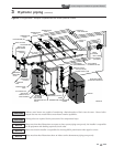
4 Gas connections (continued)
Outdoor Knight XL Installation & Operation Manual