


15
RELIEF VALVE
FLOW SWITCH
PADDLE
TEMPERATURE &
PRESSURE GAUGE
TEE WITH FITTING
(FIELD PROVIDED)
CLOSE NIPPLE
(FIELD PROVIDED)
TEE WITH 1" FITTING
ON TOP
CLOSE NIPPLE
TEE WITH 3/4"
FITTING ON TOP
IMG00389
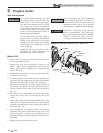
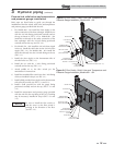
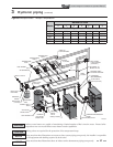
NOTICE
Be sure to install the fl ow switch so
that the arrow on the fl ow switch is
pointing in the direction of the fl ow
(see FIG. 3-3).
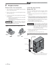
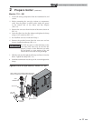
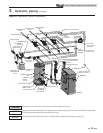
Figure 3-2 Flow Switch, Relief Valve and Temperature and
Pressure Gauge Installation_Models 601 - 801
Flow switch, relief valve and temperature
and pressure gauge installation
Basic steps are listed below to guide you through the
installation of the fl ow switch, relief valve, and temperature
and pressure gauge provided with the unit.
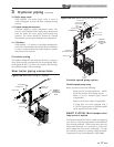
1. For Models 400 - 501 install the close nipple on the
outlet connection of the heat exchanger. Install the tee
with the 3/4 inch fi tting positioned vertically and on
the top as shown in FIG. 3-1. For Models 601 - 801
install the tee directly to the outlet connection of the
heat exchanger with the 3/4 inch fi tting positioned
vertically and on the top (see FIG. 3-2).
2. For Models 701 - 801 install the 3/4 inch close nipple
in the tee. Install the relief valve on the 3/4 inch close
nipple (FIG. 3-2). For Models 400 - 601 install the
relief valve directly into the 3/4 inch fi tting on the tee
(FIG. 3-1).
3. Install the close nipple on the downstream side of
the relief valve tee (FIG. 3-1).
4. Install the tee with the 1 inch fi tting positioned
vertically and on the top (FIG. 3-1).
5. Attach paddle #3 to the fl ow switch per the
manufacturer’s instructions.
6. Install the assembled fl ow switch into the 1 inch fi tting
of the tee installed in Step 4 (see FIG. 3-1).
7. Install a fi eld provided close nipple on the downstream
side of the fl ow switch (see FIG.’s 3-1 and 3-2).
8. Install a fi eld provided tee with the gauge fi tting
positioned vertically and on the top (FIG.’s 3-1 and
3-2)
9. Install the temperature and pressure gauge provided
with the unit into the top fi tting of the tee (a bushing
may be necessary) installed in Step 8 (FIG.’s 3-1 and
3-2).
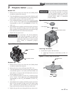
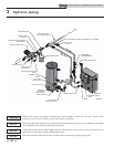
RELIEF VALVE
FLOW SWITCH
PADDLE
TEMPERATURE &
PRESSURE GAUGE
TEE WITH FITTING
ON TOP
(FIELD PROVIDED)
CLOSE NIPPLE
(FIELD PROVIDED)
TEE WITH 1" FITTING ON TOP
CLOSE NIPPLE
TEE WITH 3/4"
FITTING ON TOP
8' NIPPLE
(REQUIRED FOR MODELS 400 - 701)
IMG00390
Figure 3-1 Flow Switch, Relief Valve and Temperature and
Pressure Gauge Installation_Models 400 - 501
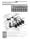
3 Hydronic piping (continued)
Outdoor Knight XL Installation & Operation Manual