


16
Outdoor Knight XL Installation & Operation Manual
3 Hydronic piping
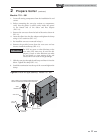
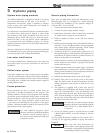
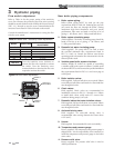
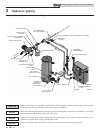
Figure 3-3 Flow Switch Adjustment
Flow switch adjustment
Refer to Table 3A for the proper setting of the sensitivity
screw. For reference, the position of the screw prior to setting
should be turned clockwise with a Phillips driver until it stops
(FIG. 3-3). Proceed to turn the screw counterclockwise the
amount of turns listed in Table 3A based on the model.
Consult the manufacturer’s instructions for wiring the fl ow
switch to your system.
NORMALLY
OPEN
SENSITIVITY
ADJUSTMENT
NORMALLY
CLOSED
COMMON
GROUND
NOTICE
Turn the sensitivity screw clockwise to
increase the fl ow rate required to activate
the switch. Turn the sensitivity screw
counterclockwise to decrease the fl ow rate
required to activate the switch.
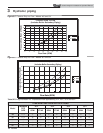
MODEL PADDLE SIZE
SENSITIVITY SCREW
ADJUSTMENT
Note: Paddles are included with the fl ow switch.
400 #3 7½ turns
501 #3 5½ turns
601 #3 7¼ turns
701 #3 5¼ turns
801 #3 3¼ turns
Table 3A Paddle Size / Sensitivity Screw Adjustment
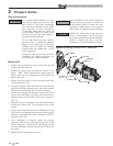
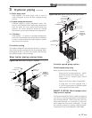
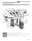
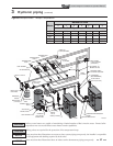
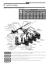
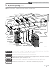
Near boiler piping components
1. Boiler system piping:
Boiler system piping MUST be sized per the pipe
requirements listed in Table 3B. Reducing the pipe size
can restrict the fl ow rate through the boiler, causing
inadvertent high limit shutdowns and poor system
performance. Flow rates are based on 20 feet (6 m) of
piping, 4 - 90° elbows, and 2 - fully ported ball valves.
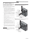
2. Boiler system circulating pump:
(Field supplied.) The boiler circulating pump should be
based on 20 feet (6 m) of piping, 4 - 90° elbows, and
2 - fully ported ball valves.
3. Domestic hot water circulating pump:
(Field supplied.) The pump MUST be sized to meet
the specifi ed minimum fl ow requirements listed in
FIG.’s 3-5 and 3-6. Consult the indirect water heater
operating guide to determine fl ow characteristics for the
selected product used.
4. Variable speed boiler system circulator:
Outdoor Knight XL boilers are capable of controlling
a variable speed boiler system circulator. Variable speed
circulators MUST be sized to meet the specifi ed minimum
fl ow requirements listed in FIG.’s 3-5 and 3-6 on page 16
at full speed.
5. Boiler isolation valves:
Field supplied. Full port ball valves are required. Failure
to use full port ball valves could result in a restricted fl ow
rate through the boiler.
6. Check valves:
Field supplied. Check valves are recommended for
installation as shown in FIG.’s 3-7 through 3-11. Failure
to install check valves could result in a reverse fl ow
condition during pump(s) off cycle.
7. Domestic indirect hot water isolation valves:
Field supplied. Full port ball valves are required. Failure
to use full port ball valves could result in a restricted fl ow
rate through the boiler.
8. Anti-scald mixing valve:
Field supplied. An anti-scald mixing valve is
recommended when storing domestic hot water above
115°F (46°C).
9. Unions:
Field supplied. Recommended for unit serviceability.
10. Temperature and pressure gauge:
Factory supplied. The temperature and pressure gauge is
shipped loose. It is the responsibility of the contractor to
install the temperature and pressure gauge on the boiler
water outlet.
11. Pressure relief valve:
Factory supplied. The pressure relief valve is sized to
ASME specifi cations.