


28
Outdoor Knight XL Installation & Operation Manual
5 Field wiring
ELECTRICAL SHOCK HAZARD – For
your safety, turn off electrical power
supply before making any electrical
connections to avoid possible electric
shock hazard. Failure to do so can cause
severe personal injury or death.
Wiring must be N.E.C. Class 1.
If original wiring as supplied with boiler
must be replaced, use only type 105°C
wire or equivalent.
Boiler must be electrically grounded as
required by National Electrical Code
ANSI/NFPA 70 – latest edition.
Ensure that all wiring external to the
unit is enclosed in approved conduit.
Installation must comply with:
1. National Electrical Code and any other national, state,
provincial, or local codes, or regulations.
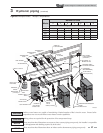
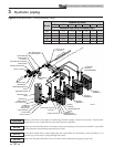
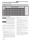
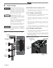
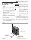
Line voltage connections
1. Connect 120 VAC power wiring to the line voltage terminal
strip in the junction box, as shown in FIG.5-1.
2. Provide and install a fused disconnect or service switch
(15 amp recommended) as required by the code (see
FIG. 5-1).
3. When connecting a domestic hot water (DHW) pump,
connect the wiring to the line voltage terminal strip as
shown in FIG. 5-1.
4. To activate a system pump, wire as shown in FIG. 5-1. Dry
contacts are sized for 1.5 hp/120V, 3 hp/240V or 30 amps.
DOMESTIC
HOT WATER
PUMP
BOILER
PUMP
SYSTEM
PUMP
120V SUPPLY
LINE
GROUND
NEUTRAL
W
G
BK
SERVICE
SWITCH
L2/N
G
L1
BK
G
W
BK
G
W
BK
G
W
Figure 5-1 Line Voltage Field Wiring Connections
Label all wires prior to disconnection
when servicing controls. Wiring errors
can cause improper and dangerous
operation.
ƽ WARNING
NOTICE
ƽ CAUTION
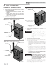
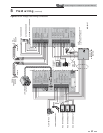
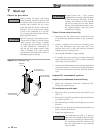
Low voltage connections
1. Route all low voltage wires through the knockouts in the
rear of the boiler, as shown in FIG. 5-2.
2. Connect low voltage wiring to the low voltage connection
board as shown in FIG. 5-3 on page 29 of this manual and
the boiler wiring diagram.
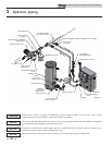
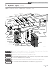
LINE VOLTAGE
JUNCTION BOX
LOW VOLTAGE
CONNECTION
BOARD
LOW VOLTAGE
WIRING
KNOCKOUT
PLUGS
LINE VOLTAGE
WIRING KNOCKOUT
PLUGS
IMG00329
Figure 5-2 Routing Field Wiring