


20
Outdoor Knight XL Installation & Operation Manual
3 Hydronic piping
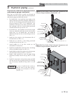
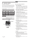
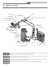
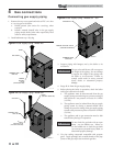
Figure 3-8 Single Boiler - Primary/Secondary Piping
NOTICE
System fl ow should always remain higher than the required fl ow for the boiler(s) when the boiler(s) is in
operation to prevent short cycling and high limit issues.
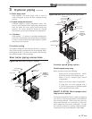
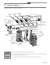
Please note that these illustrations are meant to show system piping concept only, the installer is responsible
for all equipment and detailing required by local codes.
NOTICE
CAUTION
Indirect water heaters are capable of transferring a limited number of Btu’s into the water. Ensure boiler
output does not not exceed indirect water heater transfer capabilities.
EXPANSION TANK
AIR SEPARATOR
PRESSURE REDUCING
VALVE
BACK FLOW
PREVENTER
BALL VALVE
(TYPICAL)
UNION (TYPICAL)
PRESSURE RELIEF
VALVE
FLOW CHECK
VALVE (TYPICAL)
INDIRECT DHW
TANK
BOILER
DRAIN
DRAIN POINT
(TYPICAL)
BOILER CIRCULATOR
COLD WATER IN
ANTI-SCALD
MIXING VALVE
SYSTEM SUPPLY SENSOR
(WHEN USED)
SYSTEM CIRCULATOR
T
O
S
Y
S
T
E
M
F
R
O
M
S
Y
S
T
E
M
DOMESTIC
HOT WATER
CIRCULATOR
HOT WATER OUT
MAKE UP WATER
NOT TO EXCEED 4 PIPE DIA OR MAX. OF 12" APART
Y-STRAINER
(RECOMMENDED)
MAY SUBSTITUTE
LOW LOSS HEADER
IMG00393
Please note that these illustrations show an indoor tank to demonstrate piping concept only.
NOTICE