


1 Service
23
Service Manual
1 Service (continued)
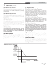
Cascade Off-On Differential
This parameter determines how much the temperature must
go below the turn off temperature (Set point + Offset) before
the lead boiler turns on. This parameter can be adjusted by the
installer by accessing parameter J4.
Maximum Boiler Set Point for Cascade
This parameter determines the set point used by the individual
boilers in a Cascade. When a boiler is commanded to fire by
the Leader boiler, it will attempt to achieve this temperature
at its outlet. If any of the boiler outlet temperatures reach the
maximum cascade set point, the boiler will then modulate
down on its own in order to keep its outlet temperature within
the maximum cascade set point. Therefore, this parameter
can be used to limit the outlet temperatures of all the boilers
in a Cascade. Note that this parameter does not apply when
the boiler is heating an indirect HWG tank. This parameter is
adjustable by the installer by accessing parameter J5.
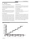
Cascade Type
The Cascade divider method is Efficiency Optimization,
designated as EFF in the menu. This method is used, as the
name implies, when it is desired to have the most efficient
system. When the first boiler reaches a certain rate (default =
80%), it lowers its rate to 40% and turns on the next boiler at
40%. The two (2) boilers then modulate at the same rate. As
the calculated load increases further and both boilers ramp up
to 80%, it lowers the rate of the first two (2) boilers to 53%
and brings the next boiler on at 53%. The three (3) boilers
then modulate together. As the calculated load decreases, the
boilers will reach a lower threshold (default = 10%), at which
time the last boiler (the third in our example) will turn off and
the Cascade will increase the rates of the remaining boilers to
provide the equivalent total output as before ((3 x 10%) / 2 =
15% in our example). This parameter can be adjusted by the
installer by accessing parameter J6.
Minimum On/Off Time
In order to prevent units in a Cascade from short cycling, this
parameter defines the minimum ON and OFF time for each
unit. The installer can adjust this time by accessing parameter
J7.
I: ModBus
ModBus (Active / Inactive)
When BMS is set to ACTIVE (see BMS Active / Inactive)
and the boiler is being controlled through ModBus, set
parameter I1 to ACTIVE. Otherwise, set the ModBus
parameter to INACTIVE. Note that the boiler can still
be monitored by ModBus with this parameter set to
INACTIVE.
ModBus Out of Order Timer
When the boiler is being provided with certain commands
and temperatures through ModBus, this information must
be updated frequently. If it is not updated before this
timer expires, the boiler will revert back to its own internal
readings and control. This parameter is adjustable by the
installer by accessing parameter I2.
J: Cascade
Cascade Active / Inactive
The boiler is part of a group of units sequenced together. The
designated Leader unit determines the total output needed
from the group based on the set point and controlling
sensor reading. It assigns portions of the output to itself
(Leader) and the Member units. When Cascade is active,
each boiler in the group requires a unique address. This
setting is adjustable by the installer by accessing parameter
J1.
Cascade Address
The boiler designated as the Leader needs to be programmed
with address 0. All the Member boilers require addresses
from 1 to 7, and the addresses must be different for each
Member. The addresses can be in any order, regardless
of the order in which the units are wired together. This
parameter is adjustable by the installer by accessing
parameter J2. The outdoor air (if used) and system supply
sensor must be connected to the Leader boiler.
Cascade Offset
This parameter determines how much the temperature
can go above set point before the lead boiler will turn off.
This parameter can be adjusted by the installer by accessing
parameter J3.