


3 Troubleshooting
36
Service Manual
Label all wires prior to disconnection
when servicing controls. Wiring
errors can cause improper and
dangerous operation. Always
disconnect power to the boiler
before servicing. Failure to comply
could result in severe personal
injury, death, or substantial
property damage.
Never jumper (bypass) any device
except for momentary testing as
outlined in the Troubleshooting
chart. Severe personal injury, death,
or substantial property damage can
result.
Before troubleshooting:
1. Have the following items:
a. Voltmeter that can check 120 vac, 24 vac, and
12 vdc.
b. Continuity checker.
c. Contact thermometer.
2. Check for 120 vac (minimum 102 vac to maximum
132 vac) to boiler.
3. Make sure thermostat is calling for heat and
contacts are closed. Check for 24 vac between
thermostat wire nuts and ground.
4. Make sure all external limit controls are installed
and operating.
Check the following:
1. Wire connectors to control module are securely
plugged in at the module and originating control.
2. Gas pressures:
• Maximum: 14 inches w.c. (3.5 kPa) (natural and
LP) with no flow (lockup) or with boiler on
• Minimum: 4 inches w.c. (1.0 kPa) (natural and
LP), with gas flowing (verify during boiler
startup)
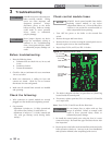
Check control module fuses
ALWAYS check control module fuses before
replacing control module or any major
components (blower, etc.). If one of these fuses
is blown, it can prevent the control module or
other components from operating.
1. Turn OFF the power to the boiler at the external line
switch.
2. Remove the upper and lower doors.
3. Remove the four (4) screws securing the control panel cover to
the unit to gain access to the control module.
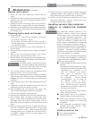
4. Inspect fuses F2, F4, and F5, see FIG 3-1 below.
F2 - 3.15 AMP
BLOWER RELAYS
F4 - 5 AMP
PUMP RELAYS
F5 - 5 AMP
IGNITOR OUTPUT
F6 - 5 AMP
NOT USED
(SPARE)
Figure 3-1 Control Module Fuses
5. The boiler is shipped with four (4) spare fuses in a plastic bag
located inside the control panel.
6. If necessary, replace open fuse (F2 is 3.15 amps, F4, F5 and F6
are 5 amps each).
Note: Fuses F2, F4, F5 and F6 are all slow blow fuses.
Do not jumper fuse or replace with any fuse
except as specified. Failure to comply could
result in severe personal injury, death, or
substantial property damage.
7. Re-install the control panel cover using the four (4) screws
removed in Step 3. Re-install the upper and lower doors after
fuse inspection.
8. Restore power to the boiler at the external line switch and verify
boiler operation (Section 9 - Start-up in the Crest Installation
and Operation Manual) after completing boiler service.
ƽ WARNING
ƽ WARNING
NOTICE
ƽ WARNING