


1 Service (continued)
Service Manual
E: BMS
BMS (Active / Inactive)
The set point or modulation of the boiler may be controlled
through the 0 - 10V BMS input or through ModBus. When
parameter E1 set to INACTIVE, the 0 - 10V input will be
ignored. When set to ACTIVE, the set point or modulation
will be controlled by the voltage on the 0 - 10V input (in
the case of 0 - 10V BMS control), or the 0 - 10V input value
received through ModBus.
BMS Mode (Power / Set Point)
When programmed for BMS control through the 0 - 10V
BMS input or through ModBus, the 0 - 10V signal can be
interpreted as either a modulation command or a set point.
When parameter E2 is set to POWER, the 0 - 10V signal
will control the modulation. When set to SETPOINT, the
0 - 10V signal will control the SH set point.
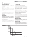
BMS Volts at Minimum (Rate or Set Point)
When programmed for BMS control through the 0 - 10V
BMS input or through ModBus, parameters E3 or E7
should be set to the minimum voltage signal sent to the
SMART TOUCH control.
BMS Volts at Maximum (Rate or Set Point)
When programmed for BMS control through the 0 - 10V
BMS input or through ModBus, parameter E4 or E8 should
be set to the maximum voltage signal sent to the SMART
TOUCH control.
BMS Rate at Minimum Volts
When programmed for BMS control through the 0 -
10V BMS input or through ModBus and the BMS Type
is programmed as POWER, the modulation percentage
represented by the Volts at Minimum parameter (E3) is set
by parameter E5.
BMS Rate at Maximum Volts
When programmed for BMS control through the 0 -
10V BMS input or through ModBus and the BMS Type
is programmed as POWER, the modulation percentage
represented by the Volts at Maximum parameter (E4) is set
by parameter E6.
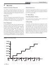
BMS Set Point at Minimum Volts
When programmed for BMS control through the 0 - 10V
BMS input or through ModBus and the BMS Type is
programmed as SETPOINT, the set point represented by
the Volts at Minimum parameter (E7) is set by parameter
E9.
21
BMS Set Point at Maximum Volts
When programmed for BMS control through the 0 - 10V BMS
input or through ModBus and the BMS Type is programmed as
SETPOINT, the set point represented by the Volts at Maximum
parameter (E8) is set by parameter E10.
BMS Volts to Enable
When programmed for BMS control through the 0 - 10V BMS
input or through ModBus and the BMS Enable Mode is set to
INACTIVE, parameter E11 determines the 0 - 10V BMS input
voltage at which the boiler is enabled.
Differential to Stop BMS Demand
When programmed for BMS control through the 0 - 10V BMS
input or through ModBus and the BMS Enable Mode is set to
INACTIVE, parameter E12 determines how far below the On
Volts setting E11 the 0 - 10V BMS input voltage must be in
order to disable the boiler.
BMS Enable Mode
When controlling the boiler through the 0 - 10V BMS input or
through ModBus, the boiler can be enabled one of two ways.
With parameter E13 set to ACTIVE, the boiler will be enabled
by closing the Enable input. When parameter E13 is set to
INACTIVE, the boiler will be enabled by the voltage level on the
0 - 10V input (in the case of 0 - 10V BMS control), or the 0 - 10V
input value received through ModBus.
F: Advanced Setup
Temperature units (°C / °F)
The control can be configured to display temperature in either
°C or °F. This parameter can be changed by the user or the
installer by accessing parameter F1.
Display Timeout (LCD Backlight Time)
This is the time in which the display remains illuminated.
This parameter can be changed by the user or the installer by
accessing parameter F2.
Freeze Protection Pump On
The SMART TOUCH control will turn on the boiler and system
pump outputs whenever the inlet temperature drops below this
setting. This is done to prevent the water in the heat exchanger
from freezing. Certain low-temperature applications (such as
snow melt) can operate at temperatures around freezing, so
this setting needs to be lowered in these cases. The installer can
adjust the temperature at which the pump outputs are turned on
by accessing parameter F3.