


46
Installation & Service Manual
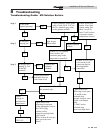
Check All Wiring
1. Inspect all wiring, making sure wires are in good
condition and securely attached.
Check Control Settings
1. Adjust settings if necessary. See Section 5 - Electrical
Connections for adjustment procedures.
2. Check settings of external limit controls (if any) and
adjust if necessary.
Check Burner Flame
Visually check main burner flames at each start-up after long
shutdown periods or at least every six months. A burner
viewport is located on the burner mounting flange.
Perform Start-up and Checks
1. Start appliance and perform checks and tests specified in
Section 6 - Start-up.
2. Verify cold fill pressure is correct and that operating
pressure does not go too high.
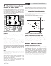
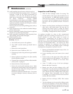
The area around the burner viewport is
hot and direct contact could result in
burns.
ƽ WARNING
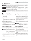
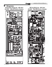
NORMAL
A
YELLOW TIP
B
D
FLAME LIFT
C
YELLOW FLAME
ƽ WARNING: The area around the burners is hot and direct contact could result in burns!
Figure 7-1_Flame Pattern Illustration
Normal Flame: A normal flame is blue, with slight yellow
tips, with a well defined inner cone and no flame lifting.
Yellow Tip: Yellow tip can be caused by blockage or partial
obstruction of air flow to the burner(s).
Yellow Flames: Yellow flames can be caused by blockage of
primary air flow to the burner(s) or excessive gas input. This
condition MUST be cor rect ed immediately.
Lifting Flames: Lifting flames can be caused by over firing the
burner(s) or excessive primary air.
If improper flame is observed, examine the venting system,
ensure proper gas supply and adequate supply of combustion
and ventilation air.
Combustion Air
This ap pli ance uses an atmospheric combustion process.
Combustion air is provided to the burners by the gas injection
pressure into the venturi of the burn ers. The burners do not
have an adjustable air shutter. Ad e quate combustion air must be
supplied to the room where the appliance is installed to ensure
proper burner operation. Check frequently to be sure the flow
of com bus tion and ventilation air to the unit is not obstructed.
When the main burn ers light, observe the burn er flame. Flames
should be light blue in color with slight yellow tips; flames
should be settled on burner head with no lifting when supplied
with correct vol ume of combustion air.
Check Flue Gas Passageways
Any sign of soot around the outer jacket, at the burn ers or in the
areas between the fins on the cop per heat exchanger indicates a
need for cleaning. The following cleaning procedure must only
be per formed by a qualified serviceman or installer. Prop er
service is required to maintain safe operation. Properly installed
and ad just ed appliances sel dom need flue cleaning.
All gaskets on disassembled components
must be replaced with new gaskets on
re as sem bly. Gasket kits are available from
your distributor.
NOTICE
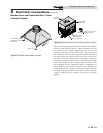
Heat Exchanger / Burner Access
ƽ WARNING
The combustion chamber insulation in this
appliance contains ceramic fiber material.
Ceramic fibers can be converted to
cristobalite in very high temperature
applications. The International Agency for
Research on Cancer (IARC) has concluded,
“Crystalline Silica in the form of quartz or
cristobalite from occupational sources is
carcinogenic to humans (Group 1).” Normal
operating temperatures in this appliance are
below the level to convert ceramic fibers to
cristobalite. Abnormal operating conditions
would have to be created to convert the
ceramic fibers in this appliance to
cristobalite.
The ceramic fiber material used in this
appliance is an irritant; when handling or
replacing the ceramic materials it is
advisable that the installer follow these safety
guidelines:
7 Maintenance