


Installation & Service Manual
13
2 Venting
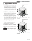
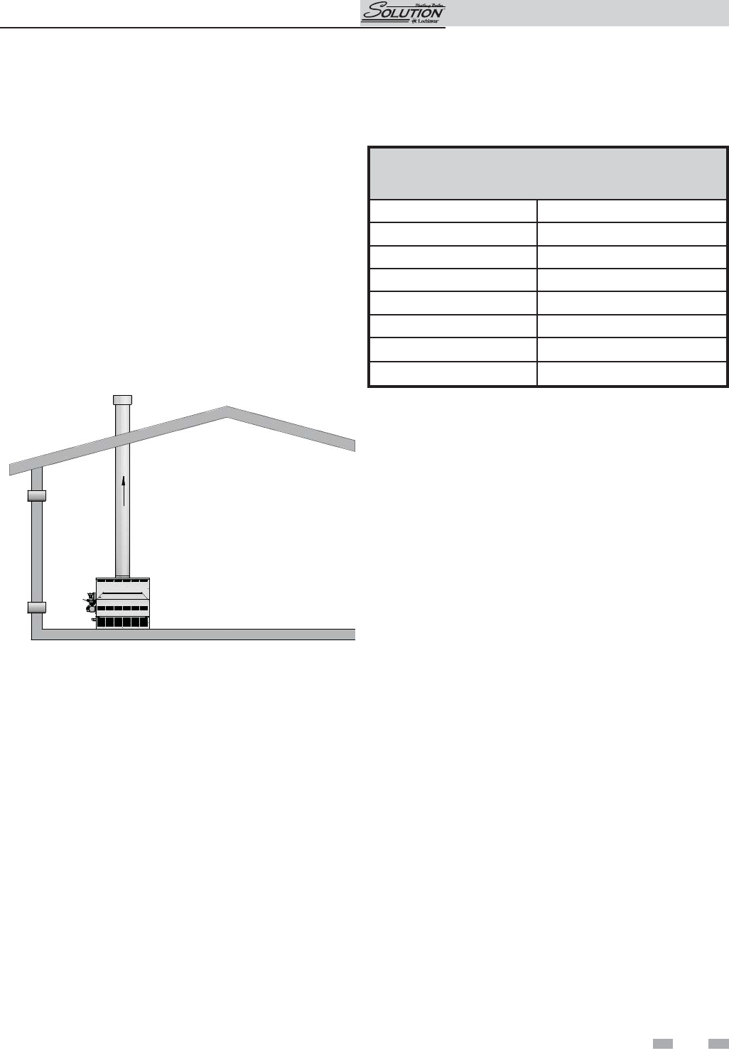
A Conventional Negative Draft
Venting System
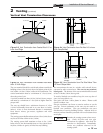
The negative draft in a conventional vent in stal la tion must be
within the range of a negative 0.02 to 0.05 inches water
column to ensure proper operation. All draft read ings are
made while the appliance is in stable op er a tion
(approximately 2 to 5 minutes).
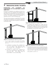
Multiple appliance installations with combined vent ing or
common venting with other negative draft ap pli anc es require
that each appliance must have draft with in the proper range.
If the draft mea sured above the appliance’s built-in draft
diverter ex ceeds the specified range in a dedicated chimney
for a single appliance installation or in combined venting with
other negative draft appliances, a baro met ric damper must be
in stalled to control draft.
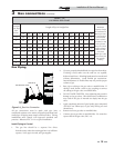
Figure 2-1_Conventional Negative Draft Vertical Venting
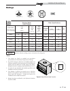
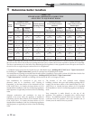
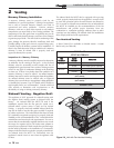
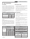
TABLE - 2A
VENT PIPE SIZES
Input Btu/hr Flue Size
45,000 4"
75,000 5"
90,000 5"
135,000 6"
180,000 7"
215,000 7"
260,000 8"
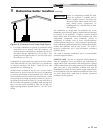
On a conventionally vented, negative draft ap pli ance, the
connection from the vent to the chimney or vent termination
on the outside of the building MUST be made with listed Type
“B” double wall (or equivalent) vent connectors and must be
direct as possible with no reduction in diameter. Use the
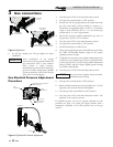
National Fuel Gas Code venting tables for dou ble wall vent to
properly size all vent connectors and stacks. The Type “B” vent
and accessories, such as firestop spacers, thim bles, caps, etc.,
MUST be installed in accordance with the manufacturer’s
list ing. The vent connector and firestop must provide correct
spacing to combustible surfaces and seal to the vent connector
on the upper and lower sides of each floor or ceiling through
which the vent connector passes.
Any vent materials used must be listed by a na tion al ly
recognized test agency for use as vent ma te ri al.