


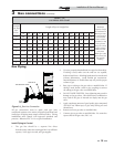
Circulator Pump Specifications
1. Maximum operating pressure for the pump must exceed
system operating pressure.
2. Maximum water temperature should not ex ceed
nameplate rating.
3. Cast iron circulators may be used for closed loop
systems.
4. A properly sized expansion tank must be in stalled near
the boiler and located on the suction side of the pump.
PUMP INSTALLATION AND MAIN TE NANCE: The boiler
circulating pump must be purchased lo cal ly. For installation
and maintenance information on the circulator pump, refer to
the pump man u fac tur ers in struc tion package included with
the pump.
4 Water connections (continued)
27
Installation & Service Manual
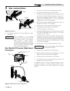
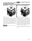
TO PERFORMANCE
LOOP PUMP (OPT.)
TO
CIRCULATION
PUMP
120V
SUPPLY
TO
UNIT
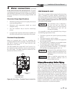
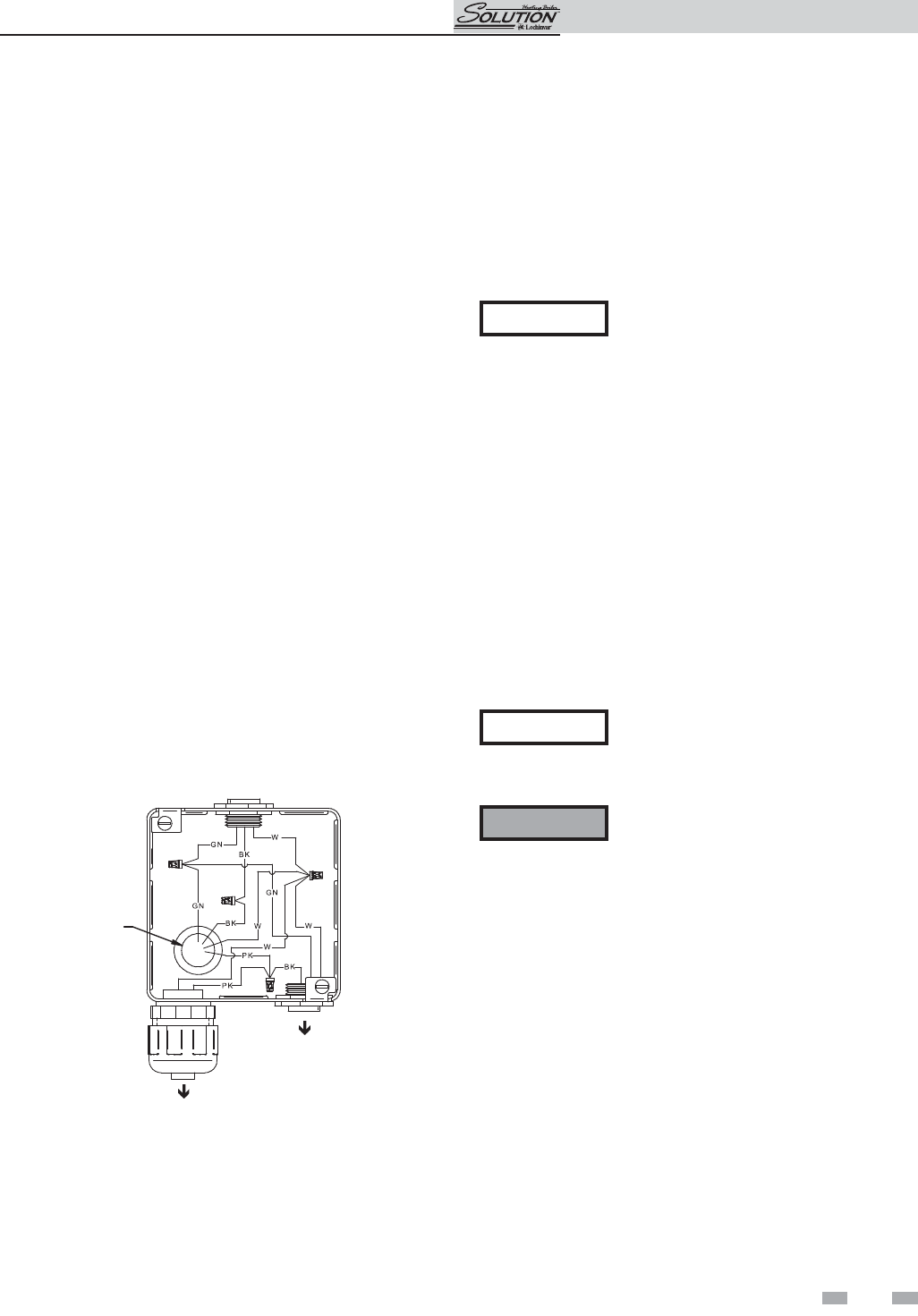
Figure 4-3_Boiler Wiring - Circulation Pump to Junction Box
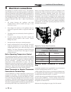
Circulator Pump Operation
Boilers are equipped with a relay for controlling the
circulation pump for the hot water loop. The relay turns ON
and OFF in response to the “W” input from the wall
thermostat or zone control.
The field installed boiler pump MUST NOT exceed 1 h.p.
For continuous pump operation, wire the system pump to
the 120V supply. The pump should be connected at the
junction box as shown in FIG. 4-3.
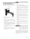
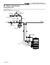
PERFORMANCE LOOP
These units are equipped with an integral performance loop,
which is designed to provide efficiency optimization by
maintaining a constant flow through the unit’s heat exchanger
loop when building system flow is reduced. The performance
loop assembly is standard equipment and is NOT to be used
as a system or boiler pump.
NOTICE
The performance loop is dedicated to
the unit and does not affect the
building’s system or primary/secondary
flow characteristics and will not
circulate the building.
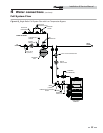
It is acceptable to remove the performance loop as long as
the following requirements are met:
1. The boiler is piped to the system in primary/secondary
fashion.
2. The system setpoint is 140°F or higher.
3. The boiler circulating pump is sized for the appropriate
flow through the boiler.
4. The system sensor is installed in an acceptable location
for sensing the system supply temperature.
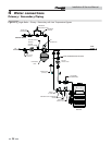
5. If water temperature is below 140°F a low temperature
bypass must be installed, (VAL30000 - 1 1/2" LTV Valve
Kit) and follow the piping diagram in FIG. 4-4.
NOTICE
If removal of the performance loop is
necessary, consult the manufacturer for
a Solution Without a Performance Loop
(KIT30068).
ƽ WARNING
Failure to install the system sensor can
cause operation problems such as
nuisance high limit trips.
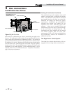
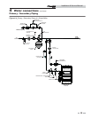
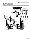
Primary/Secondary Boiler Piping
A pri ma ry/secondary pip ing system may also be in stalled to
ensure proper boiler flow rates. Primary/sec ond ary piping is
also ideal for systems using a mixture of propylene glycol and
water. A primary/secondary piping system uses a dedicated
pump to supply flow to the boiler only. This pump is sized
based on de sired boiler flow rate, boiler head loss and head loss
in the sec ond ary system piping only. The secondary pump, in -
stalled in the boiler piping, ensures a constant wa ter flow rate
to the boiler for proper operation. Boiler installation with a
primary/secondary piping sys tem can prevent noise problems
caused by low sys tem water flows. A primary/secondary piping
system is recommended on any boiler where low water flow
conditions may present an operational problem.