


Relief Valve
RELIEF VALVE
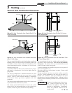
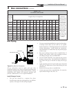
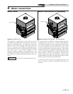
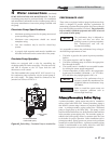
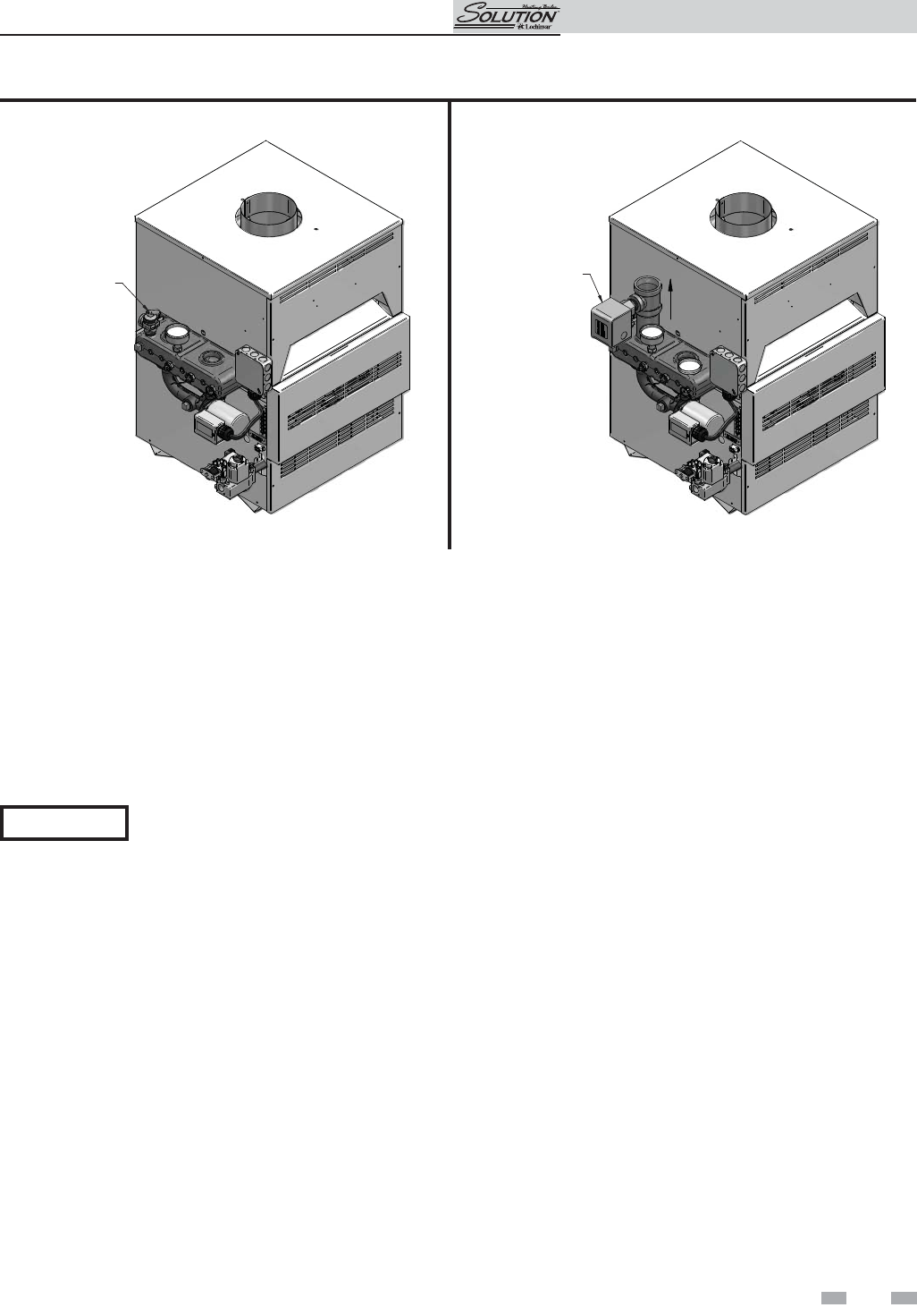
Figure 4-1_Relief Valve
This appliance is supplied with a relief valve(s) sized in
accordance with ASME Boiler and Pressure Ves sel Code,
Section IV (“Heating Boilers”). The re lief valve(s) is mounted
directly into the heat ex chang er inside the header (see
FIG. 4-1). To pre vent water damage, the dis charge from the
relief valve shall be piped to a suit able floor drain for disposal
when relief occurs. No reducing couplings or other
restrictions shall be installed in the discharge line. The
discharge line shall allow complete drainage of the valve and
line. Relief valves should be manually operated at least once
a year.
ƽ CAUTION
Avoid contact with hot discharge water.
Water Flow Switch (if equipped)
FLOW SWITCH
FLOW
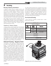
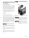
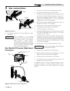
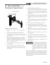
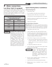
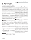
Figure 4-2_Water Flow Switch - Top Connections
A water flow switch is available as a factory sup plied option on
all heating boilers (see FIG. 4-2). The flow switch should be
wired between terminals X and B. Remove the jumper between
the X and B terminals on the terminal strip. This wiring
connection installs the flow switch in the 24 VAC safety cir cuit
to prove water flow before main burner ig ni tion. A flow switch
installed with the fac to ry sup plied minimum adjustment setting
requires a spe cif ic minimum flow to make the switch and start
burner operation. The flow rate required is a function of the
diameter of pipe and tee used for installation. Ensure that the
pump installed on the boiler will supply adequate flow to make
the flow switch con tacts and operate the boil er.
A water flow switch meets most code re quire ments for a low
water cut off device on boil ers requiring forced cir cu la tion for
operation.
4 Water connections
23
Installation & Service Manual