


4
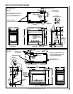
NOTE: DIAGRAMS & ILLUSTRATIONS ARE NOT TO SCALE.
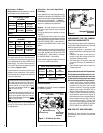
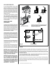
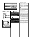
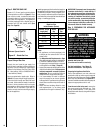
Test gauge connections are provided on the
front of the millivolt and electronic gas control
valve (identified IN for the inlet and OUT for the
manifold side). The control valves have a 3/8"
(10mm) NPT thread inlet and outlet side of the
valve (refer to Figures 1 and 2).
Propane tanks are at pressures that will cause
damage to valve components. Verify that the
tanks have step down regulators to reduce the
pressure to safe levels.
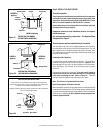
Gas Valve Diagrams
See Figure 1 for Millivolt models and Figure 2
For Electronic Models.
These appliances must not be connected to a
chimney or flue serving a separate solid fuel
burning appliance.
Manifold Gas Supply Pressure
(all models)
Fuel # Low High
Natural
Gas
(Lo) 2.2" WC
(0.55 kPa)
(Hi) 3.5" WC
(0.87 kPa)
Propane
(Lo) 6.3" WC
(1.57 kPa)
(Hi) 10.0" WC
(2.49 kPa)
Table 3
These appliances must be isolated from the
gas supply piping system (by closing their
individual manual shut-off valve) during any
pressure testing of the gas supply piping
system at test pressures equal to or less
than 1/2 psig (3.5 kPa).
These appliances and their individual shut-off
valves must be disconnected from the gas
supply piping system during any pressure
testing of that system at pressures greater
than 1/2 psig (3.5 kPa).
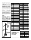
Orifice Sizes - Sea Level to High Altitude
(All Models)
These appliances are tested and approved for
installation at elevations of 0-4500 feet (0-1372
meters) above sea level using the standard burner
orifice sizes (marked with an "*" in Table 4 ).
For elevations above 4500 feet, contact your gas
supplier or qualified service technician.
Deration - At higher elevations, the amount
of BTU fuel value delivered must be reduced
by either:
• Using gas that has been derated by the gas
company.
• By changing the burner orice to a smaller
size as regulated by the local authorities having
jurisdiction and by the (USA) National Fuel Gas
Code NFPA 54/ANSI Z223.1 - latest edition or,
in Canada, the CAN/CSA-B149.1 codes - latest
edition.
Install the appliance according to the regulations
of the local authorities having jurisdiction and,
in the USA, the National Fuel Gas Code NFPA
54 / ANSI Z223.1 - latest edition or, in Canada,
the CAN/CSA-B149.1 - latest edition.
Flame breadth, height and width will diminish
4% for every 1,000 feet of altitude.
REQUIREMENTS FOR THE COMMON-
WEALTH OF MASSACHUSETTS
These fireplaces are approved for installation in
the US state of Massachusetts if the following
additional requirements are met:
• Install this appliance in accordance with
Massachusetts Rules and Regulations 248
C.M.R.
• Installation and repair must be done by a
plumber or gas fitter licensed in the Com-
monwealth of Massachusetts.
• The exible gas line connector used shall
not exceed 36 inches (92 centimeters) in
length.
• The individual manual shut-off must be a
T-handle type valve.
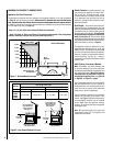
Massachusetts Horizontal Vent Requirements
In the Commonwealth of Massachusetts, hori-
zontal terminations installed less than seven
(7) feet above the finished grade must comply
with the following additional requirements:
• A hard wired carbon monoxide detector
with an alarm and battery back-up must be
installed on the floor level where the gas
fireplace is installed. The carbon monoxide
detector must comply with NFPA 720, be
ANSI/UL 2034 listed and be ISA certified.
• A metal or plastic identication plate must
be permanently mounted to the exterior of
the building at a minimum height of eight (8)
feet above grade and be directly in line with
the horizontal termination. The sign must
read, in print size no less than one-half (1/2)
inch in size, GAS VENT DIRECTLY BELOW.
KEEP CLEAR OF ALL OBSTRUCTIONS.
NEW YORK CITY, NEW YORK (MEA)
Installation of these fireplaces are approved
for installation in New York City in the US state
of New York.
Inlet Gas Supply Pressure
(all models)
Fuel # Minimum Maximum
Natural Gas
4.5" WC
(1.12 kPa)
10.5" WC
(2.61 kPa)
Propane
11.0" WC
(2.74 kPa)
13.0" WC
(3.23 kPa)
Table 2
Gas Pressure - All Models
Tables 2 and 3 show the appliances' inlet and
manifold gas pressure requirements:
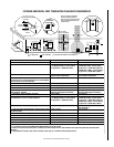
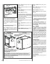
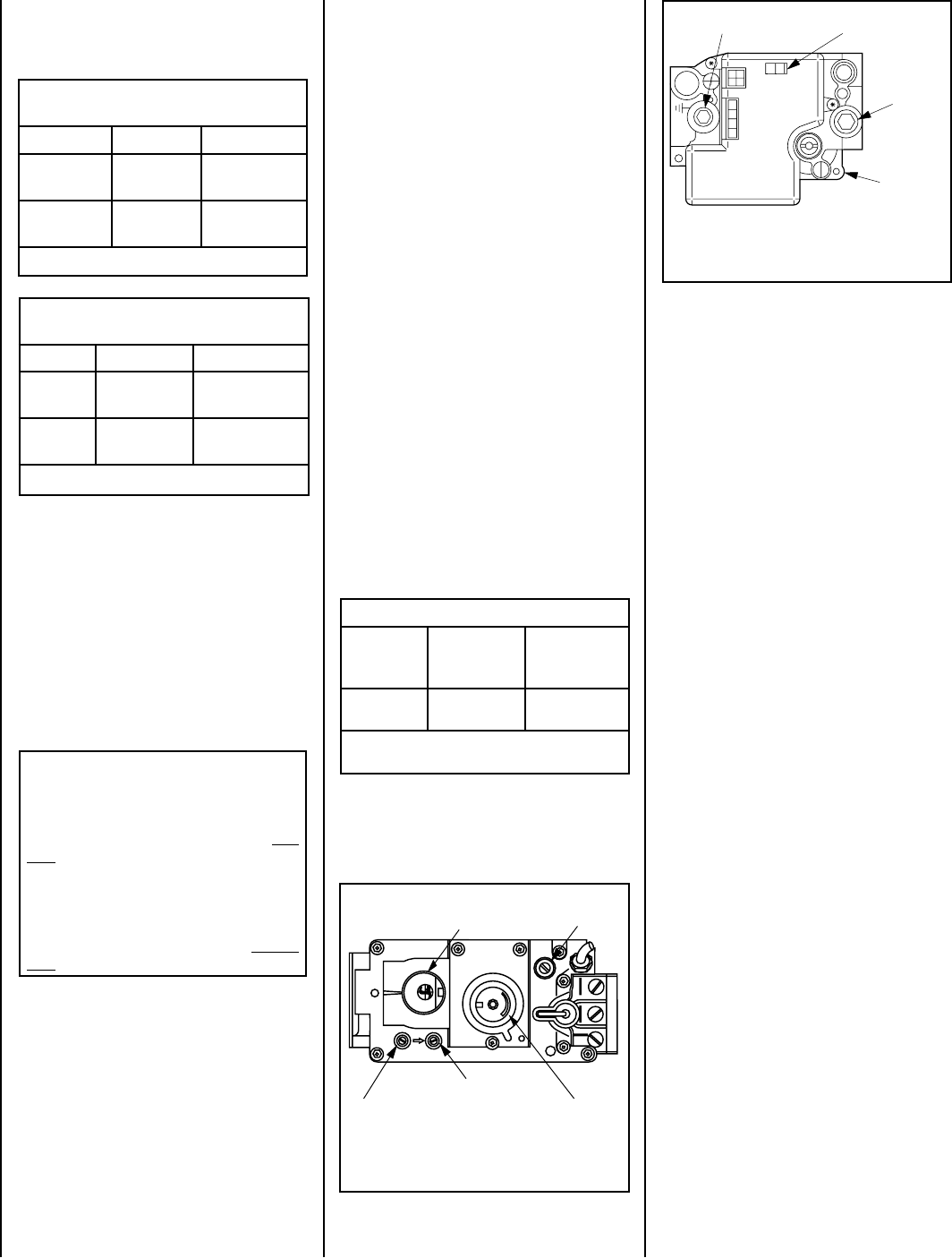
Figure 2
Honeywell Electronic
Gas Valve
ON/OFF Switch
Electronic
Gas Control
Valve
Inlet
Pressure
Port
Manifold Pressure Port
OFF
IN
PSI
ON
CONTROL
IGNITER
H
I
L
O
W
HTPTHTPT
P
I
L
O
T
P
I
L
O
T
O
N
it
O
F
F
IN
OUT
HI/LO Variable
Flame Height
Adjustment
Figure 1 - SIT Millivolt Gas Valve
Manifold Pressure Tap
Inlet Pressure Tap
Pilot Adjustment
Screw
Main Gas Control Knob
OFF/PILOT/ON
Burner Orifice Sizes (all models)
Elevation
Feet (meters)
Natural
Gas
drill size (inches)
Propane
Gas
drill size (inches)
0-4500
(0-1372)
(0.125")
*
21L81 •
#41
(0.096")
*
21L82 •
Table 4
* Standard size installed at factory
• Part /Cat. Number