


14
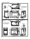
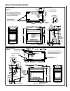
NOTE: DIAGRAMS & ILLUSTRATIONS ARE NOT TO SCALE.
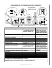
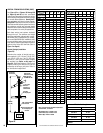
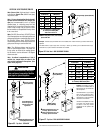
Schedule 40
Black Iron Pipe
Inside Diameter (Inches)
Schedule 40 Pipe
Length (feet)
Natural
Gas
Propane
Gas
0-10 1/2 3/8
10-40 1/2 1/2
40-100 1/2 1/2
100-150 3/4 1/2
150-200 3/4 1/2
Table 6
IMPORTANT: If propane is used, be aware that
if tank size is too small (i.e. under 100-lbs, if
this is the only gas appliance in the dwelling.
Ref. NPFA 58), there may be loss of pressure,
resulting in insufficient fuel delivery (which
can result in sooting, severe delayed ignition
or other malfunctions). Any damage resulting
from an improper installation, such as this, is
not covered under the limited warranty.
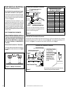
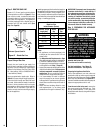
Step 3. PREPARING THE APPLIANCE
VENT COLLAR
Proper Sizing of Gas Line
Properly size and route the gas supply line
from the supply regulator to the area where the
appliance is to be installed per requirements
outlined in the National Fuel Gas Code, NFPA
54 - latest edition (USA) or CAN/CSA-B149.1
- latest edition (Canada).
Never use galvanized or plastic pipe. Refer to
Table 6 for proper sizing of the gas supply line,
if black iron pipe is being used. Gas lines must
be routed, constructed and made of materials
that are in strict accordance with local codes
and regulations. We recommend that a qualified
individual such as a plumber or gas fitter be
hired to correctly size and route the gas supply
line to the appliance.
Also see Figures 13 and 14.
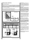
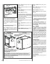
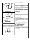
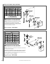
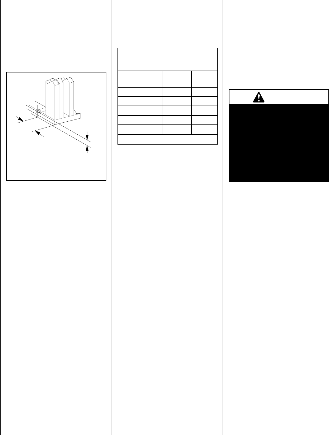
Figure 21 - Route Gas Line
Step 2. ROUTING GAS LINE
Route a 1/2" (13 mm) gas line to the left side
of the appliance as shown in Figure 21. Gas
lines must be routed, constructed and made
of materials that are in strict accordance with
local codes and regulations. All appliances
are factory-equipped with a flexible gas line
connector and 1/2 inch shutoff valve. (See
Step 7 on Page 28).
Installing a gas supply line from the fuel supply to
the appliance involves numerous considerations
of materials, protection, sizing, locations, con-
trols, pressure, sediment, and more. Certainly no
one unfamiliar and unqualified should attempt
sizing or installing gas piping.
5-5/8"
(143 mm)
3-1/8"
(79 mm)
Notes:
• All appliances are factory-equipped with
a flexible gas line connector and 1/2 inch
shutoff valve.
• See Massachusetts Requirements on Page
4 for additional requirements for installations
in the state of Massachusetts in the USA.
• The gas supply line should Not be connected
to the appliance until Step 7 (Page 28).
• A pipe joint compound rated for gas should be
used on the threaded joints. Ensure propane
resistant compounds are used in propane
applications. Be very careful that the pipe
compound does not get inside the pipe.
• It is recommended to install a sediment
trap in the supply line as close as possible
to the appliance. Appliances using Propane
should have a sediment trap at the base of
the tank.
• Check with local building ofcial for local
code requirements (i.e. are below grade
penetrations of the gas line allowed?, etc).
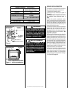
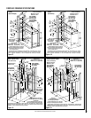
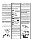
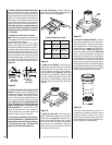
REMOVE VENT SEAL CAP
(From the vent that will be used only)
Top Vent Installations - See Figure 22
Side Vent Installations - See Figure 23
Preparing the Appliance Vent Collar
Each of the appliances' two vent collars are
sealed with a seal cap which must be removed
from the vent collar being used. Refer to Figure
22 for top vent installations and Figure 23 for
side vent installations and the following steps to
prepare the appropriate collar for use.
From the vent collar being used, remove the
two screws securing the vent seal cap. Twist
the cap counterclockwise. Pull it away from
the appliance and discard, along with the piece
of insulation.
WARNING
Failure to reinstall and securely
tighten vent seal cap screws
could result in leakage of flue
products into the living space.
Vent seal cap must remain
securely installed on unused
vent collar. Failure to do so
could result in leakage of flue
products into living space.