


13
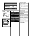
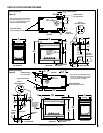
NOTE: DIAGRAMS & ILLUSTRATIONS ARE NOT TO SCALE.
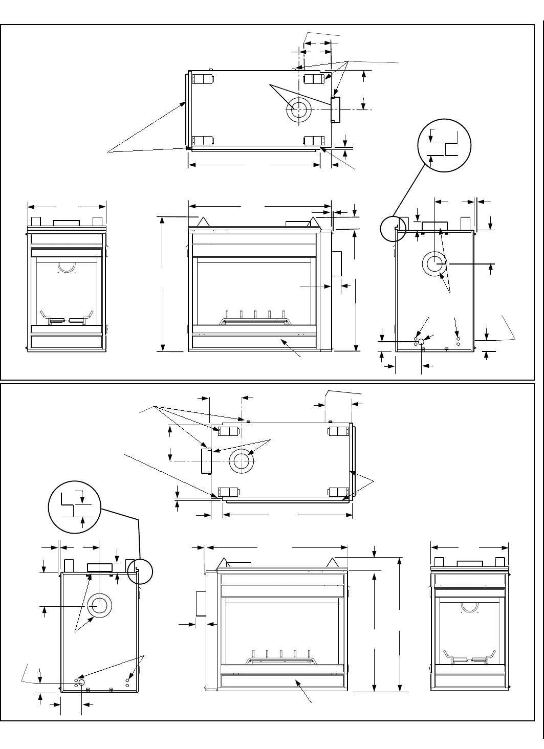
41
(1041)
37
(940)
43-5/8
(1108)
6-7/8
(175)
10-1/4
(260)
12
(305)
12 (305)
10
(254)
1/2 13)
(63.6)
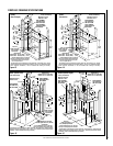
FRONT VIEW
RIGHT SIDE VIEW
LEFT SIDE VIEW
TOP VIEW
3 (76)
4 (102)
FLUE
(Top or Side)
40-1/8
(1019)
3-1/2
(89)
FLUE
(Top or Side)
GAS
INLET
ELECTRICAL
INLETS
5/8
(16)
Stepped to
Accept Drywall
FRAMING SPACERS
(Top, Side and Back)
1/2
(13)
DETAIL OF
FINISH WALL BRACKET
FINISH WALL BRACKET
(Front and left edge of unit top)
CONTROL COMPARTMENT
ACCESS PANEL
2-1/2
9-1/4
(235)
OPTIONAL GAS INLET
OPTIONAL
GAS INLET AT
CABINET REAR
3 (76)
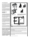
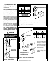
NOTE - Unit has a factory-installed vent seal
cap and vent cover plate (see Figures 22 and
23 on page 15) in each flue outlet. The vent
seal cap is not shown in this figure.
(63.6)
2-1/2
Provide Additional
Space For Side
Vent Seal Cap If
Installing Against
A Solid Wall
1/2
(13)
24
(610)
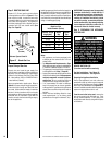
EDVCL (Corner-Left)
FLUE
(Top or Side)
6-7/8
(175)
10-1/4
(260)
12
(305)
2-1/2
(63.5)
3 (76)
FLUE
(Top or Side)
41
(1041)
37
(940)
43-5/8
(1108)
24
(610)
12 (305)
10
(254)
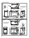
FRONT VIEW
LEFT SIDE VIEW
TOP VIEW
4 (102)
40-1/8
(1019)
3-1/2
(89)
ELECTRICAL
INLETS
5/8
(16)
Stepped to Accept Drywall
FRAMING SPACERS
(Top, Side and Back)
1/2
(13)
DETAIL OF
FINISH WALL BRACKET
RIGHT SIDE VIEW
FINISH WALL BRACKET
(Front and right edge of unit top)
9-7/8
(251)
Gas Line Location
2-1/2
(63.5)
GAS INLET
AT REAR
OF UNIT
CONTROL COMPARTMENT
ACCESS PANEL
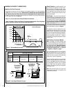
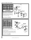
NOTE - Unit has a factory-installed vent seal
cap and vent cover plate (see Figures 22 and
23 on page 15) in each flue outlet. The vent
seal cap is not shown in this figure.
Provide Additional
Space For Side
Vent Seal Cap If
Installing Against
A Solid Wall
1/2
(13)
1/2
(13)
EDVCR (Corner-Right)
Figure 20
Figure 19
FIREPLACE SPECIFICATIONS CONTINUED