


28
NOTE: DIAGRAMS & ILLUSTRATIONS ARE NOT TO SCALE.
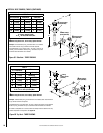
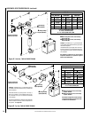
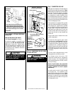
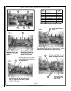
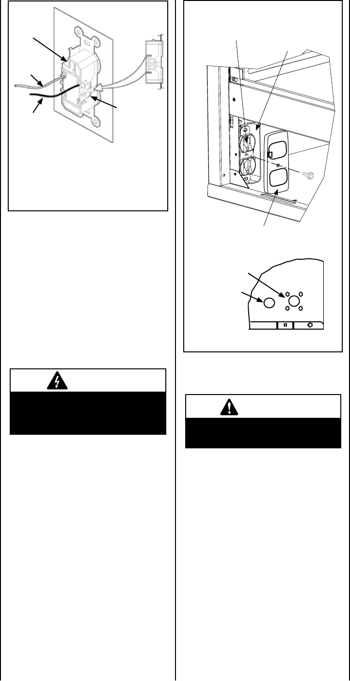
Note: Supply wires may be alternatively con-
nected to the outlet using the screw terminals,
however the black supply wire must be wired to
a terminal that is opposite (across the outlet) the
point where the white supply wire is connected.
Bipolar
Terminal
Screw
Ground Wire
Connection
White
(supply)
Black
(supply)
Figure 52
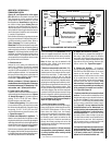
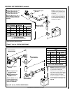
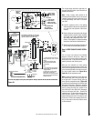
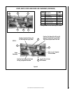
Step 6. WIRING - OPTIONAL FORCED AIR
BLOWER KIT
FBK-100, FBK-200 and FBK-250 Kits
(See Figure 54 on page 29 for wiring) -
An electrical receptacle is provided for the
installation of the FBK-100, FBK-200 and FBK-
250 forced air blower kits. Electrical power
must be connected to this receptacle in order
to operate these blowers. Install the blower
kits according to the installation instructions
provided with the kits.
Outlet Receptacle
Junction Box
Field-provided Metal Junction Box
Cover Plate With Screw
View Of Left
Bottom Corner Of Unit
Receptacle, Junction Box
and Cover Plate Installation
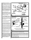
Fireplace
Side
Junction Box
knock-out (2
places each side)
Valve Access Side
Latching magnet
not shown
Press snap
bushing into the
knock-out for
control switch
wires.
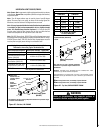
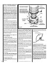
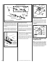
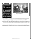
Step 7. CONNECTING GAS LINE
Make gas line connections. All codes require a
shut-off valve mounted in the supply line. Figure
55 illustrates two methods for connecting the
gas supply. The flex-line method is acceptable
in the U.S., however, Canadian requirements
vary depending on locality. Installation must
be in compliance with local codes. A sediment
trap is recommended in the gas piping within
the home to prevent moisture and debris in the
line from damaging the valve.
These appliances are equipped with a gas flex
line for use (where permitted) in connecting the
unit to the gas line. A gas flex line is provided
to aid in attaching the direct vent appliance to
the gas supply. The gas flex line can only be
used where local codes permit. The flex line
is rated for both natural and propane gas. A
manual shut off valve is also provided with
the flex line.
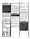
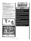
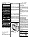
The gas control valve is located in the lower
control compartment.
To access the valve open the lower control
compartment door (see Figure 56 ) by pushing
in the right top corner of the door. (The door
is hinged at the bottom.) Remove the bottom
compartment door by sliding the hinge pin,
located at the door’s left side, to the right until
it disengages from the left corner post hole.
Pull the door diagonally to the left, away from
the fireplace.
The lower control compartment door on the
side opposite the valve lifts on and off.
The millivolt control valve has a 3/8"
(10 mm) NPT thread inlet port. The electronic
control valve has a 1/2" (13 mm) NPT thread
inlet port and is fitted with a 1/2" x 3/8" (13 mm x
10 mm) NPT fitting.
Secure all joints tightly using appropriate
tools and sealing compounds (ensure propane
resistant compounds are used in propane
applications).
All codes require a shut-off valve mounted
in the supply line. The orientation of the
shut-off valve should face the front. Figure
55 illustrates two methods for connecting the
gas supply. A sediment Trap is recommended
to prevent moisture and debris in the gas line
for damaging the valve.
Figure 53
CAUTION
Remove the carton support from
the control compartment before
operating the appliance.
WARNING
Never use an open flame to
check for leaks.
TEST ALL CONNECTIONS FOR GAS LEAKS
(FACTORY AND FIELD):