


10
NOTE: DIAGRAMS & ILLUSTRATIONS ARE NOT TO SCALE.
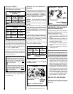
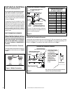
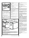
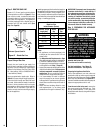
Figure 11
REMOVE
CARDBOARD
BEFORE USING
Pressure Relief
Plates
Remove Cardboard Before
Using Appliance
REMOVE
CARDBOARD
BEFORE USING
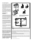
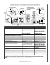
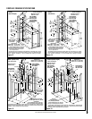
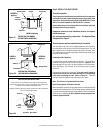
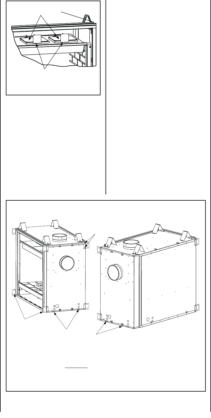
Figure 12 - Nailing Flanges
TYPICAL INSTALLATION SEQUENCE
The typical sequence of installation is outlined
below. However, each installation is unique
and may result in variations to the steps
described.
See the page numbers references in the follow-
ing steps for detailed procedures.
Step 1. (Page 10) Construct the appliance
framing. Position the appliance within the
framing and secure with nailing brackets (refer
to Figure 12).
Step 10. (Page 34) Install glass door as-
sembly.
Step 11. (Page 34) Adjust burner to ensure
proper flame appearance.
Step 12. (Page 36) Install the hoods.
Step 13. (Page 37) Attach Safety in Operation
Warnings.
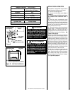
Before proceeding it may be helpful to remove
the log set form the firebox and remove the
embers and volcanic stone from the control
compartment. Refer to the following steps:
1. Remove the front glass enclosure panel
(see Removing and Installing Glass Enclosure
Panels on Page 34).
2. Remove log set box from firebox. Next,
remove embers and volcanic stone from con-
trol compartment. Handle logs carefully to
prevent breakage.
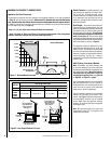
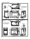
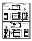
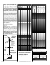
Step 1. FRAMING
Frame these appliances as illustrated in Figures
13 (EDVST), 14 (EDVPF), 15 (EDVCL) or 16
(EDVCR). All framing details must allow for
a minimum clearance to combustible framing
members as shown inTable 5 on page 9. If the
appliance is to be elevated above floor level, a
solid continuous platform must be constructed.
Headers may be in direct contact with the
appliance top spacers but must not be sup-
ported by them or notched to fit around them.
All construction above the appliance must be
self supporting, DO NOT use the appliance for
structural support.
Side Nailing Flanges
The fireplace should be secured to the framing
at the side(s) and/or rear of the unit using the
factory-provided nailing flanges. Install the
nailing flanges - 8 (EDVST), 4 (EDVPF, EDVCL
and EDVCR) - as shown in Figure 12 using the
existing screws.
Position the fireplace within the framing. When
required, the flanges may be bent 90 degrees by
hand or with the assistance of a hammer. Use
wood screws to secure the nailing flanges to
the framing. See Table 5 on page 9 for clear-
ances of framing members to cabinet parts in
the nailing flange area. The nailing flange itself
is exempt from these clearances.
Floor Nailing Tabs
Secure the fireplace to the floor as shown in
Figure 12.
Step 2. (Page 14) Route gas supply line to
appliance location.
Step 3. Preparing the appliance vent collar
(Page 14).
Step 4. (Page 15) Install the vent system and
exterior termination.
Step 5. (Page 27) Field Wiring
a. Millivolt Appliances – Install the operating
control switch (not factory provided) and bring
in electrical service line for forced air-circulating
blower (optional equipment).
b. Electronic Appliances – Field wire and install
operating control switch.
Step 6. (Page 28) Install blower kit (optional
equipment).
Step 7. (Page 28) Make connection to gas
supply.
Step 8. (Page 29) Verifying appliance opera-
tion.
Step 9. (Page 30) Install the logs, decorative
volcanic stone and glowing embers.
Turn tabs down and secure to the floor with
8d nails or other appropriate fasteners
on all sides of the unit which do not have
viewing glass panels.
EDVST SHOWN
(EDVPF - NO NAILING FLANGES
ON END WITH GLASS PANEL)
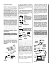
EDVCL SHOWN
(FOR EDVCR VIEW, INTERCHANGE SIDES)
Remove these two screws and
use them when installing
the nailing flanges.
Nailing Flanges
Note: The nailing flanges, combustible members and screw heads located in areas directly adjacent to the nailing
flanges, are EXEMPT from the 1/2” clearance to combustible requirements for the firebox outer wrapper
.
Combustible framing may be in
direct contact with the nailing flanges and may be located closer than 1/2” from
screw heads and the firebox wrapper in areas adjacent to the nailing flanges. Frame the opening to the exact
dimensions specified in the framing details of this manual.